
Oil-water well underground chemical agent controlling and releasing device and control method
A technology of controlled release and control method, which is applied in the field of controlled release devices for downhole chemicals in oil and water wells, can solve the problems of high one-time input, frequent chemical injection, reliability impact, etc. high coefficient effect
Patent Information
- Authority / Receiving Office
- CN · China
- Patent Type
- Applications(China)
- Current Assignee / Owner
- Publication Date
- 2021-02-23
Smart Images
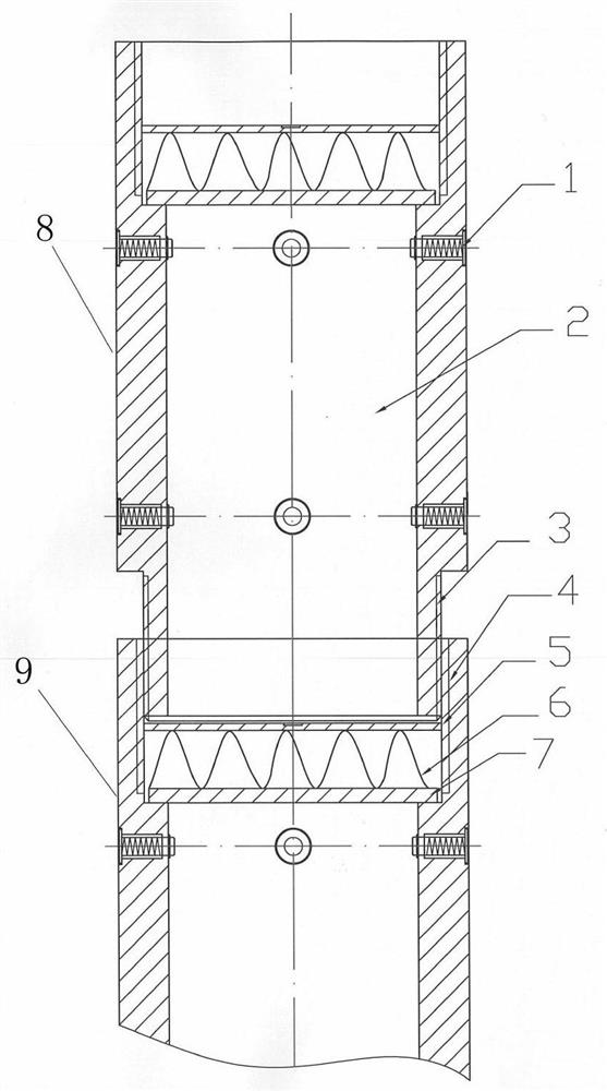
Figure 1 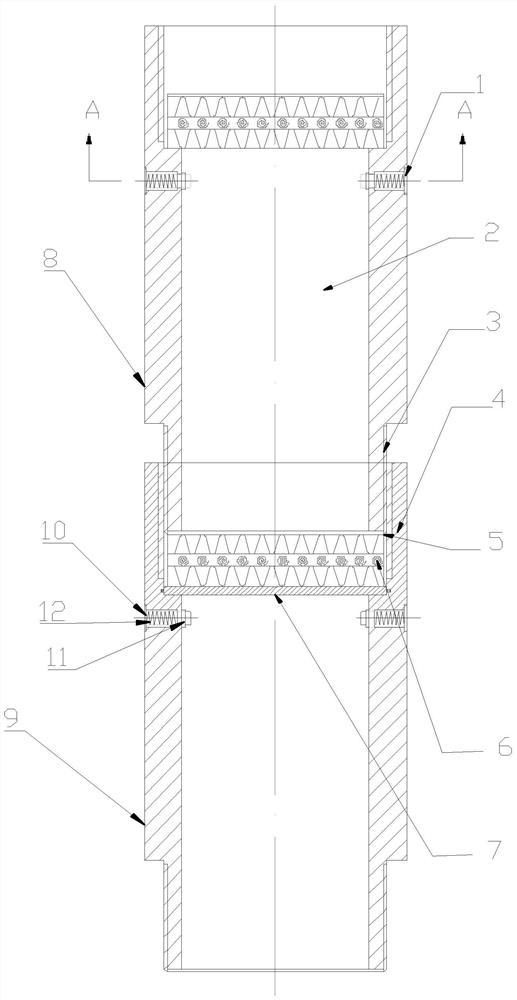
Figure 2 
Figure 3
Abstract
Description
technical field
[0001] The invention relates to the technical field of petroleum exploitation, in particular to an oil-water well downhole drug control release device and a control method. Background technique
[0002] In oil field development, oil-water wells are the most important production facilities in the water injection production development model. Due to the original colloid, wax, CO2, H2S bacteria and other corrosive components in the production medium, as well as high salinity formation water, etc., Under the downhole pressure and temperature environment, it is very easy to cause corrosion damage to the carbon steel tubing and casing, or to form scaling and wax clogging in the tubing and casing, causing the oil and water wells to stop production, increasing the workload of maintenance operations, and affecting the normal operation of the oil and water wells Production.
[0003] In order to solve the above problems, injecting chemical agents (corrosion inhibitors,...
Examples
Embodiment 1
[0038] refer to figure 1 , an oil and water well downhole drug control release device, at least including a first drug storage sub-joint 8 and a second drug storage sub-joint 9, the first drug storage sub-joint 8 and the second drug storage sub-joint 9 are both along the middle of the length direction A through hole is opened, one end of the first drug storage short joint 8 is connected to one end of the second drug storage short joint 9, and the connection between one end of the first drug storage short joint 8 and one end of the second drug storage short joint 9 A soluble partition 7 is also arranged between the end faces, and the through-hole cavity inside the first drug storage nipple 8 above the soluble partition 7 is the drug storage chamber 2 .
[0039] In the above-mentioned embodiment, when lowering the controlled drug release device, the required drug is first added to the drug storage cavity 2 in the first drug storage joint 8 located above, and then the entire firs...
Embodiment 2
[0041] refer to figure 1 , Further, an energy storage mechanism is provided above the soluble partition 7, and a fixed limit ring 5 is provided above the energy storage mechanism.
[0042] Further, the energy storage mechanism is a ring structure, and the outer diameter of the energy storage mechanism of the ring structure is equal to the diameter of the through hole in the middle of the first medicine storage short joint 8 and the second medicine storage joint 9, and the fixed limit The ring 5 is a conical ring, its conical surface is set towards the direction of the energy storage mechanism, and the outer diameter of the conical ring is 3-5mm larger than the diameter of the through hole in the middle of the first drug storage sub-joint 8 and the second drug storage sub-joint 9 .
[0043] In the above-mentioned embodiment above the soluble partition 7, the lower end of the first drug storage nipple 8 is provided with an energy storage mechanism in contact with the top of the ...
Embodiment 3
[0046] Further, refer to figure 1 and figure 2 , the first drug storage sub-section 8 and the second drug storage sub-section 9 are both circular cylindrical structures, and one end of the first drug storage sub-section 8 and the second drug storage sub-section 9 is provided with internal threads The first connecting head 4 of the first drug storage joint 8 and the other end of the second drug storage short joint 9 are provided with a second connecting head 3 which is an external thread, and the first connecting head 4 and the second connecting head 3 are both It communicates with the through hole in the middle of the first drug storage short joint 8 and the second drug storage short joint 9, the second connection head 3 of the first drug storage short joint 8 and the first connection head of the second drug storage short joint 9 4 threaded connections.
[0047] In the above-mentioned embodiment, the first drug storage sub-section 8 and the second drug storage sub-joint 9 a...