
Unloading system for an agricultural combine
Patent Information
- Authority / Receiving Office
- US · United States
- Current Assignee / Owner
- Publication Date
- 2005-02-17
Smart Images
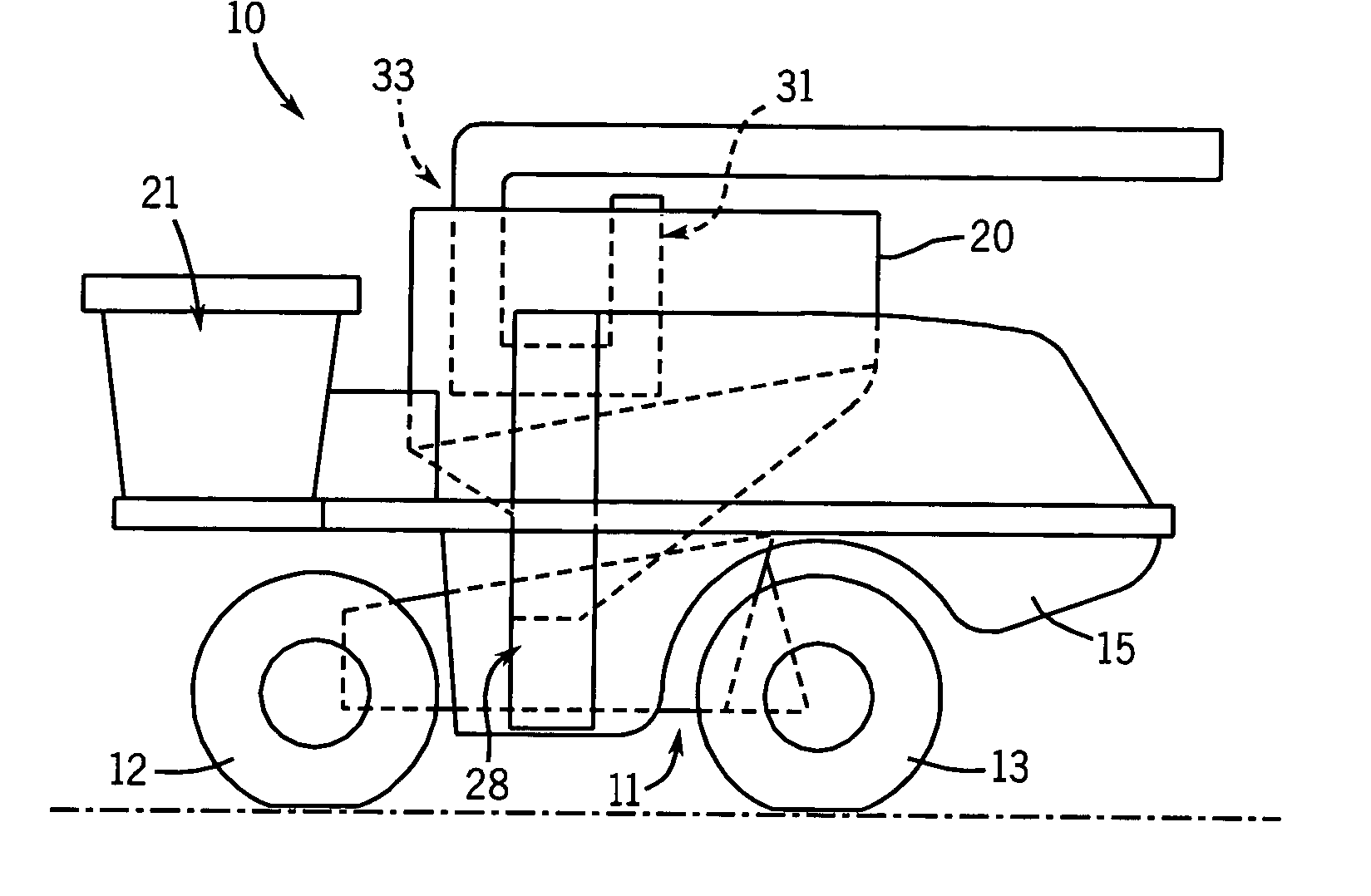
Figure 1 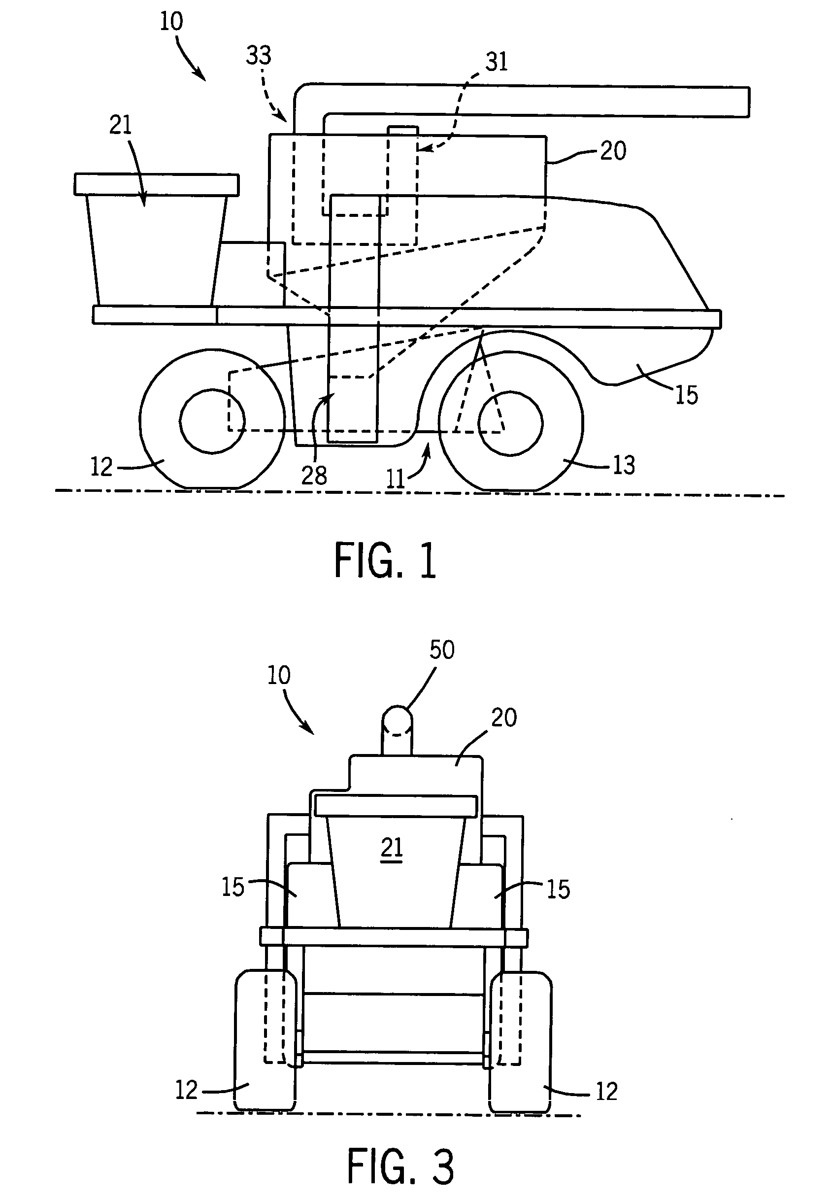
Figure 2 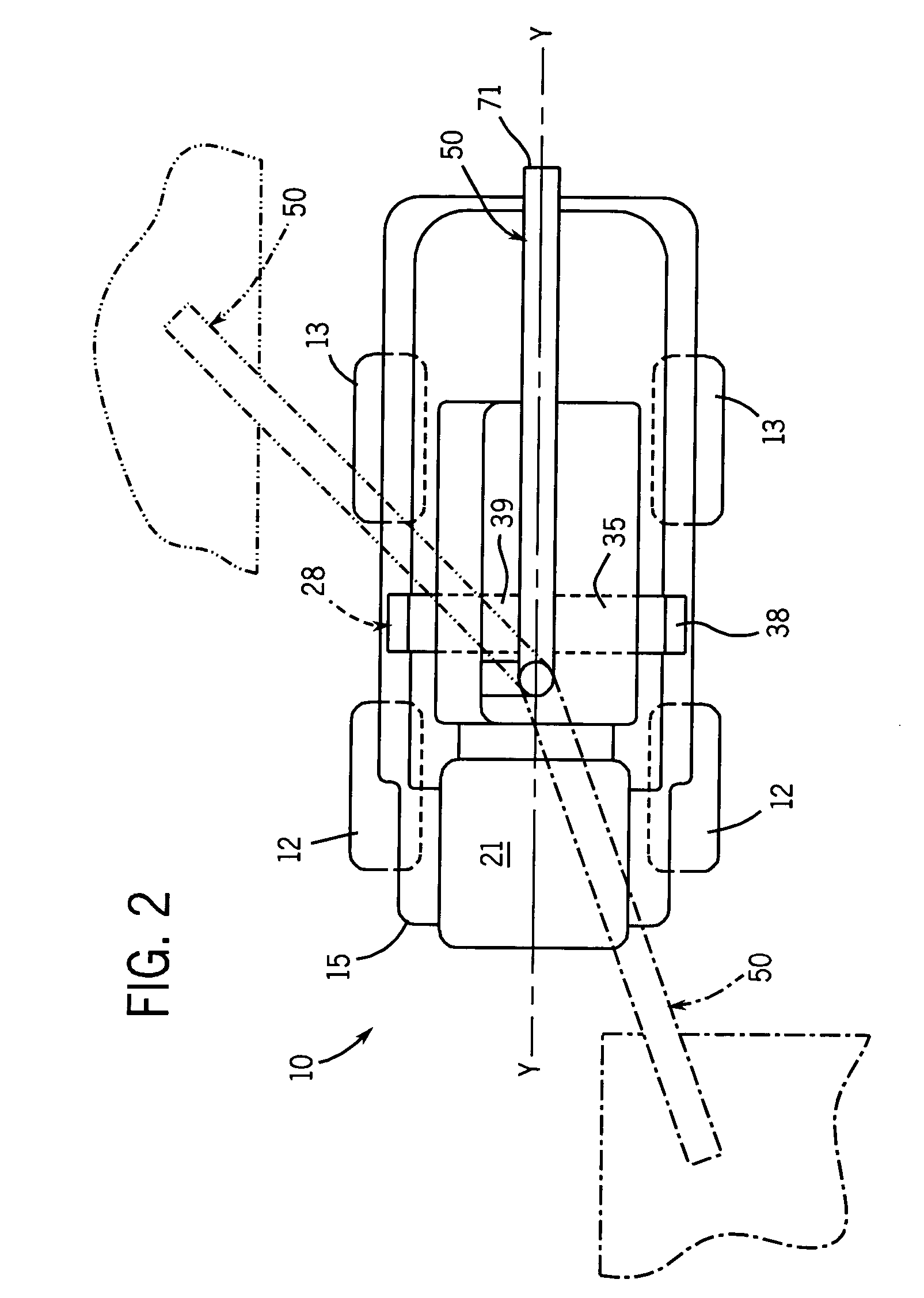
Figure 3
Abstract
Description
FIELD OF THE INVENTION
[0001] This invention relates generally to agricultural crop harvesters. It relates particularly to agricultural crop harvesters such as combines and, more specifically, to a grain unloading system for a combine. BACKGROUND OF THE INVENTION
[0002] It is conventional in combines to mount an unloading conduit on one side of the combine for swiveling movement outwardly of the combine. The inlet end of the conduit is connected to the grain tank of the combine. The outlet end of the conduit is open to permit the discharge of grain from the grain tank into a grain truck or wagon alongside the combine. A grain auger within the unloading conduit carries grain from the tank to the truck or wagon under control of the combine operator. In the alternative, the unloading conduit might contain a paddle conveyor to carry grain through it.
[0003] With a conventional unloading system, the combine can be unloaded only from one side (normally the left side) because the unloading...
Examples
Embodiment Construction
[0030] Referring now to the drawings, and particularly to FIGS. 1-3, a self-propelled, rotary combine is seen generally at 10. The combine 10 includes a chassis 11 supported by two front wheels 12 and two rear wheels 13.
[0031] The chassis 11 supports a body 15 containing an engine (not shown) which supplies power to the wheels 12 and 13, all of which are driven and steered in a manner which forms no part of the present invention. Also inside the body 15, supported by the chassis 11, is a rotary axial threshing assembly (not shown) driven from the internal combustion engine.
[0032] Above the threshing assembly, within the body 15 and extending upwardly out of the body, is a grain tank 20. In front of the body 15, adjacent the grain tank 20, is an operator's cab 21. The cab 21 is also supported from the chassis 11.
[0033] The combine 10 includes a crop harvesting header assembly (not shown). The header assembly is connected to the front end of the chassis 11 by a harvested crop feede...