
Image forming apparatus
Patent Information
- Authority / Receiving Office
- US · United States
- Current Assignee / Owner
- Publication Date
- 2012-05-31
Smart Images
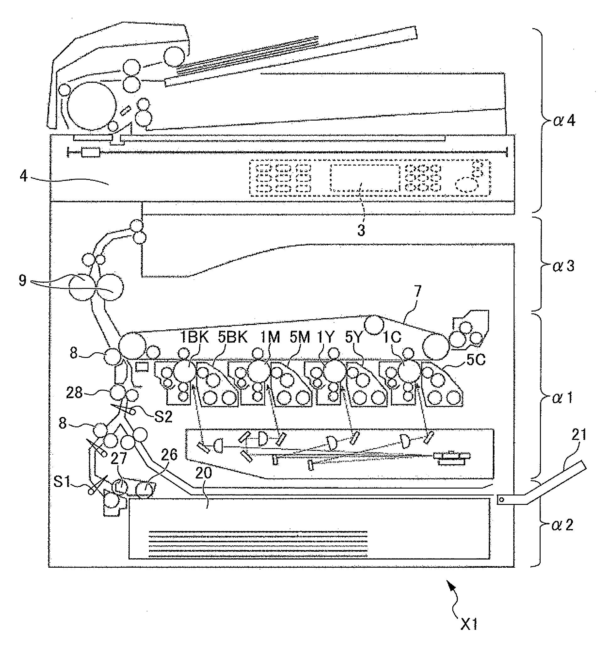
Figure 1 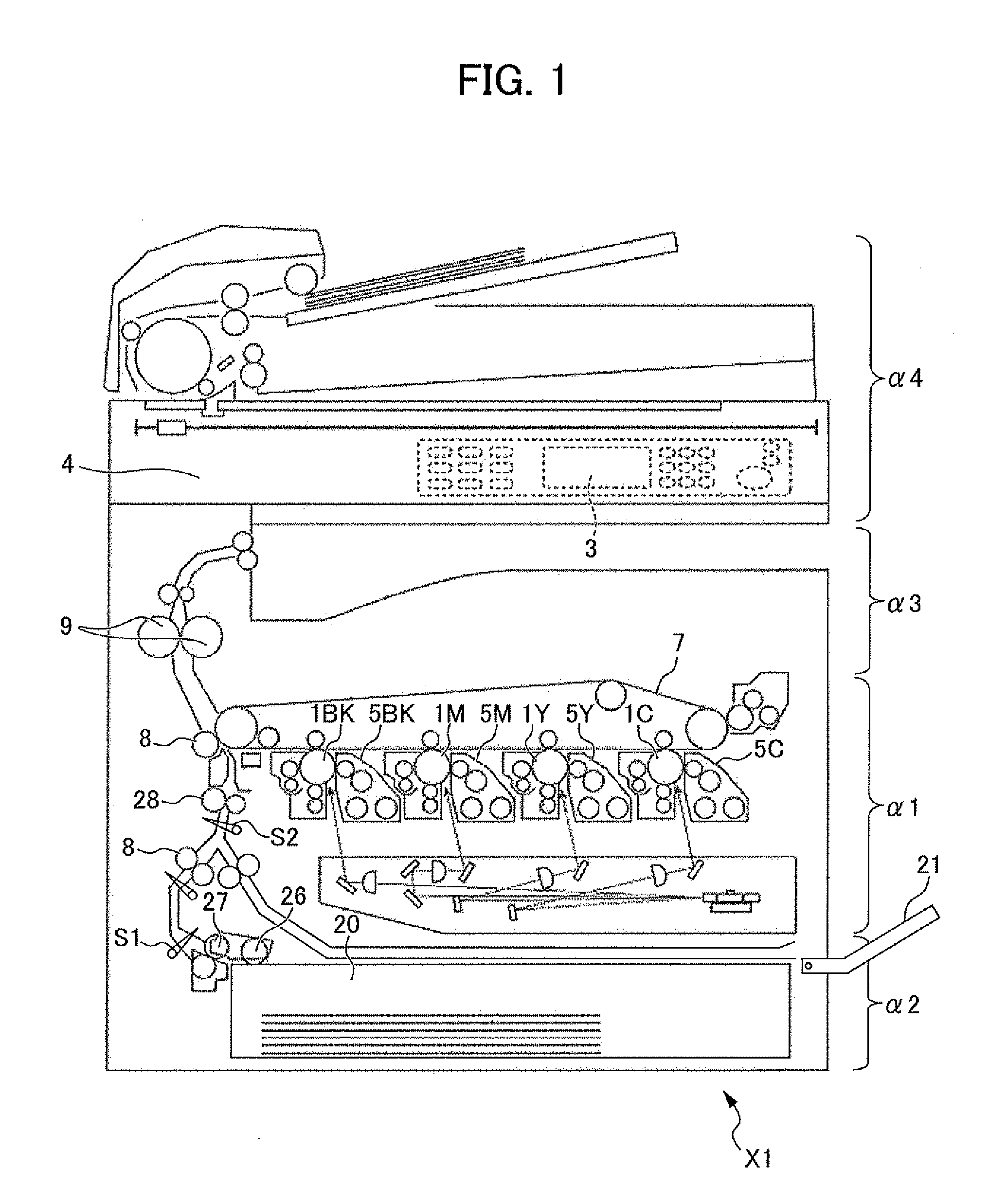
Figure 2 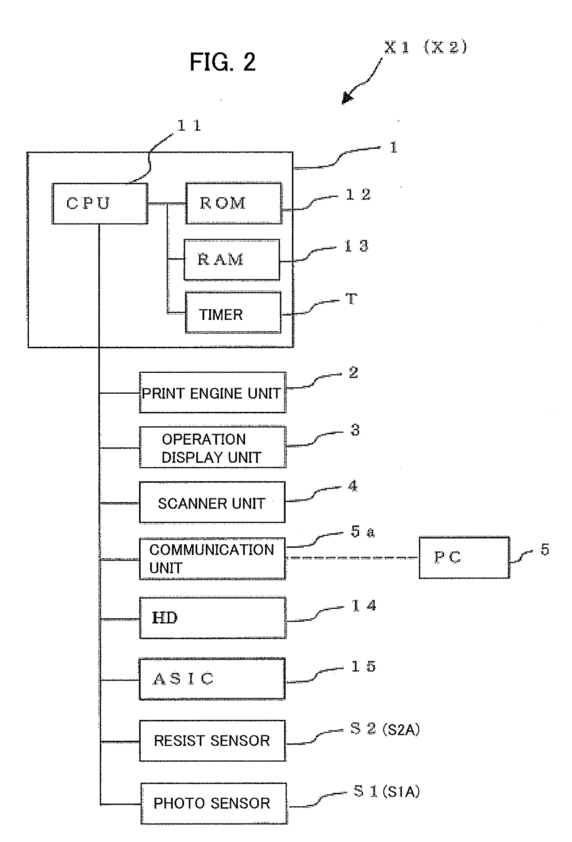
Figure 3
Abstract
Description
[0001] This application is based on and claims the benefit of priority from Japanese Patent Application No. 2010-264885, filed on 29 Nov. 2010, the content of which is incorporated herein by reference.BACKGROUND OF THE DISCLOSURE
[0002] 1. Field of the Disclosure
[0003] The present disclosure relates to an image forming apparatus that does not have paper jams or toner splatter in a case of a paper size designated by a user and the size of paper fed differing.
[0004] 2. Related Art
[0005] Conventionally, in an image forming apparatus having multiple functions, in a case of the image forming apparatus functioning as a printer, for example, information of the size of the recording paper to be used is included as a part of the image information from a personal computer. In addition, in a case of the image forming apparatus functioning as a photocopier, for example, the paper size is detected automatically by a predetermined sensor or the like.
[0006] Herein, in the case that a simplified image for...
Examples
Embodiment Construction
[0033]An embodiment of the present disclosure will be explained hereinafter while referring to the appended drawings to allow understanding of the present disclosure. It should be noted that the following embodiment is one example embodying the present disclosure, and is not characterized to limit the technical scope of the present disclosure.
[0034]The present disclosure may be equally applied in a color multifunction peripheral X1 such as that shown in FIG. 1, or a monochrome printer X2 such as that shown in FIG. 4.
[0035]First, the overall configuration of the multifunction peripheral X1 according to the embodiment of the present disclosure will be explained based on the cross-sectional view of the multifunction peripheral X1 as one example of an image forming apparatus shown in FIG. 1 and on the control block diagram shown in FIG. 2. Thereafter, the monochrome printer X2 will be explained.
[0036]The multifunction peripheral X1 is an image forming apparatus of tandem format using th...