

Hydroxy booster system
a booster system and hydroxy technology, applied in machines/engines, separation processes, filtration separation, etc., can solve the problems of engine emissions, environmental degradation, carbon monoxide, hydrocarbons and nitrogen oxides,
Patent Information
- Authority / Receiving Office
- US · United States
- Patent Type
- Applications(United States)
- Current Assignee / Owner
- Publication Date
- 2012-08-30
- Estimated Expiration
- Not applicable · inactive patent
Smart Images
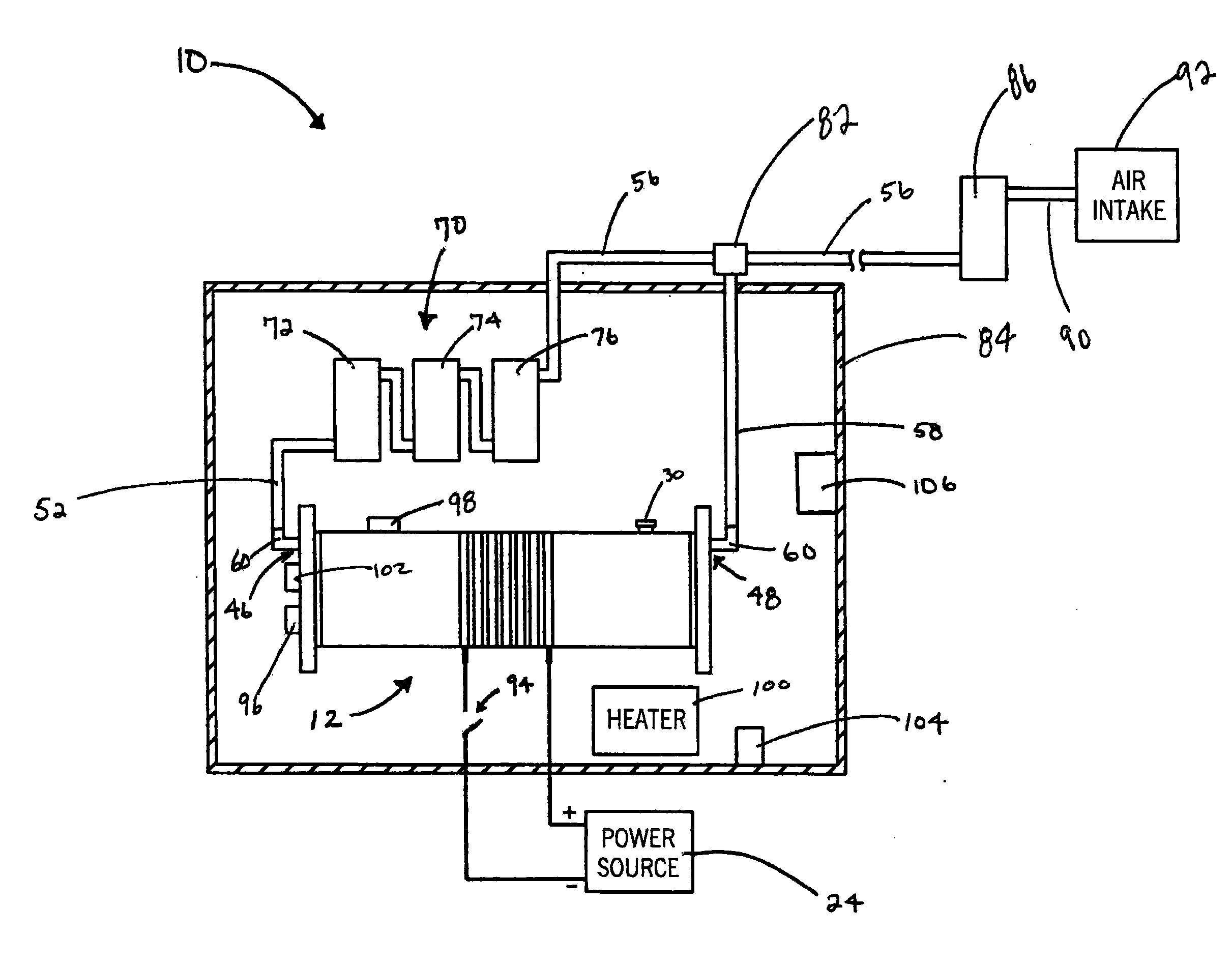
Figure 1 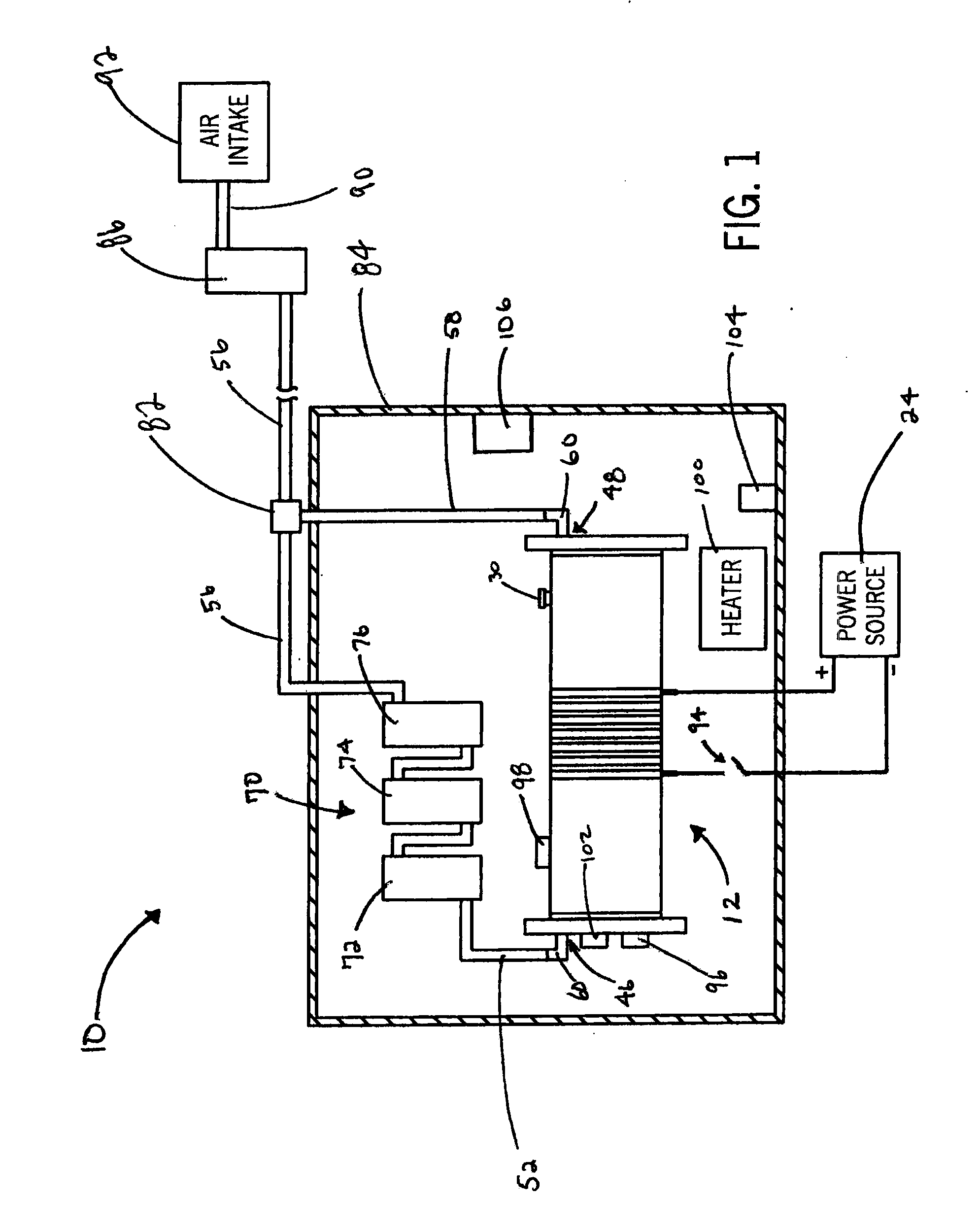
Figure 2 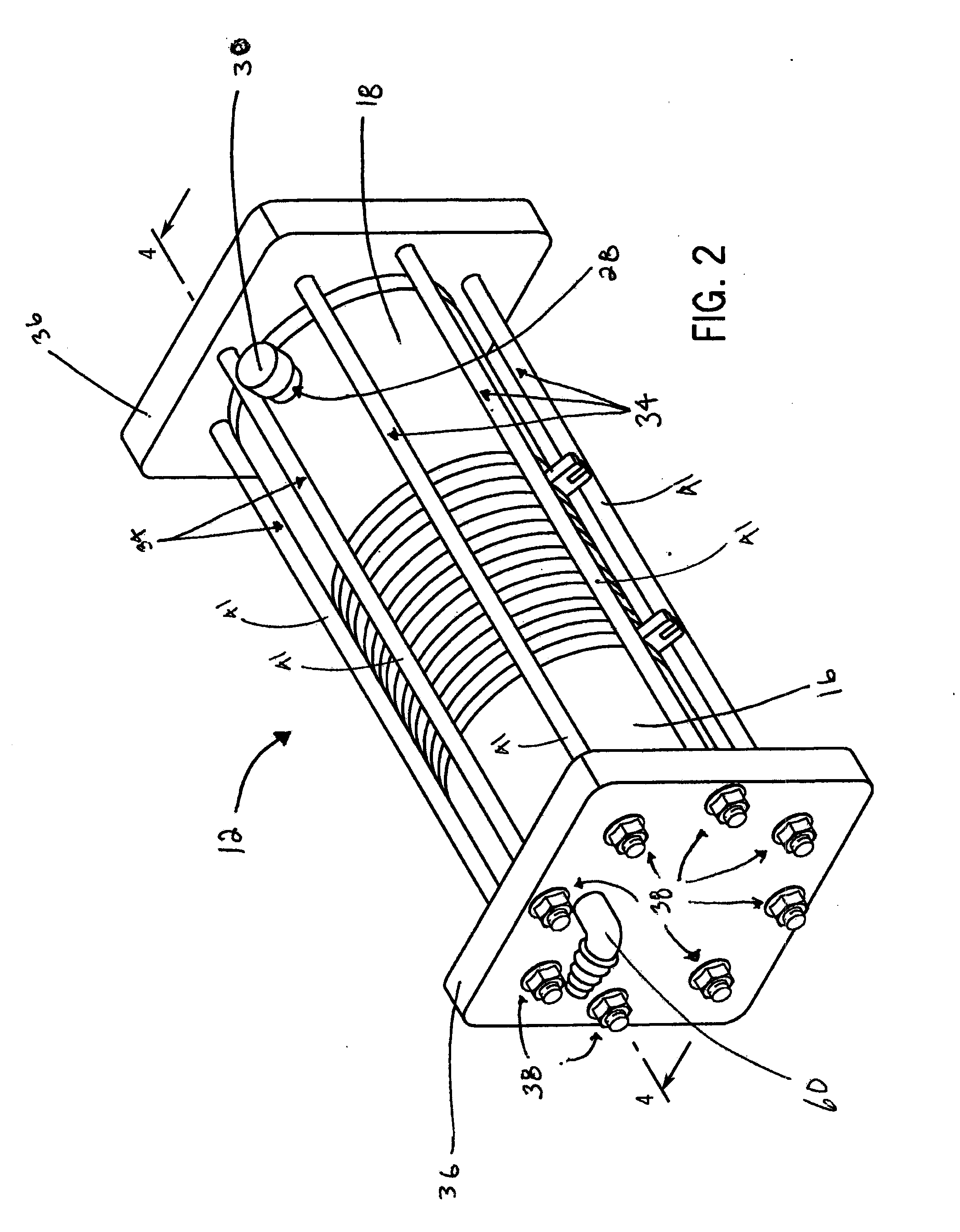
Figure 3
Abstract
Description
CROSS REFERENCE TO RELATED APPLICATIONS
[0001] This application claims the benefit of U.S. Provisional Patent Application No. 61 / 446,860 filed Feb. 25, 2011, which is incorporated in its entirety herein for all purposes.STATEMENT OF FEDERALLY SPONSORED RESEARCH OR DEVELOPMENT
[0002] Not applicable.BACKGROUND OF THE INVENTION
[0003] The invention relates to fuel supplementation systems for internal combustion engines. More specifically, the invention relates to an electrolysis system for producing a gas that includes oxygen and hydrogen to supplement the petroleum fuel supply for internal combustion engines to increase fuel efficiency and reduce harmful emissions.
[0004] Internal combustion engines are used in a wide variety of applications including, but not limited to, automobiles, busses, trucks, motorcycles, boats, aircraft, generators, and mobile equipment. These engines use a petroleum fuel supply, such as gasoline or diesel fuel. During the running cycle of such internal combustion en...
Examples
Embodiment Construction
[0027]FIG. 1 shows an electrolysis system 10 for producing oxygen and hydrogen to supplement the petroleum fuel supply of an internal combustion engine (not shown). The electrolysis system 10 includes a reservoir tank 12 that houses a solution 14 of water and electrolyte as seen in FIG. 4.
[0028]FIGS. 2 and 3 portray the components that form the reservoir tank 12 and supporting structure therefor. The reservoir tank 12 is of a cylinder-shaped construction, but it can be appreciated that the tank 12 may be constructed in other forms. The reservoir tank 12 is constructed of two tube sections 16, 18. Located between the two tube sections 16, 18 of the reservoir tank 12 are a series of plates 20a, 20b, 22a-22e.
[0029]The plates may be described as two different types of plates: battery connection plates 20a, 20b, and floater plates 22a-22e. Battery connection plates 20a, 20b are plates that are directly connected to the power source 24 (best seen in FIG. 1) and floater plates 22a-22e are...