
Portable cervical traction device
a cervical traction device and portability technology, applied in the field of cervical traction devices, can solve the problems of not typically providing support for the patient's shoulders, conventional cervical traction devices do not include a self-adjusting halter assembly, etc., and achieve the effect of maximum therapeutic benefi
Patent Information
- Authority / Receiving Office
- US · United States
- Patent Type
- Applications(United States)
- Current Assignee / Owner
- Publication Date
- 2016-01-21
- Estimated Expiration
- Not applicable · inactive patent
Smart Images
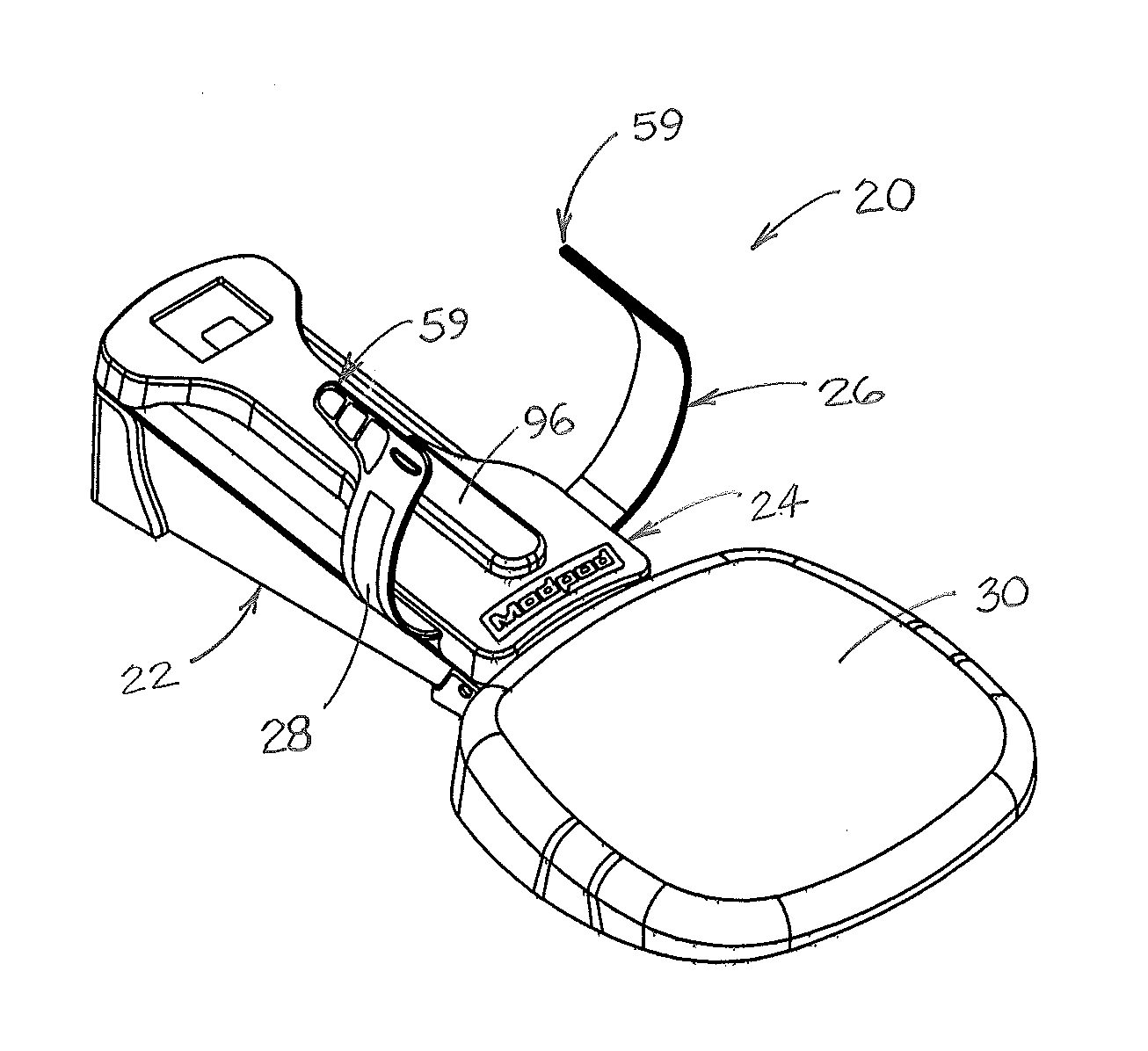
Figure 1 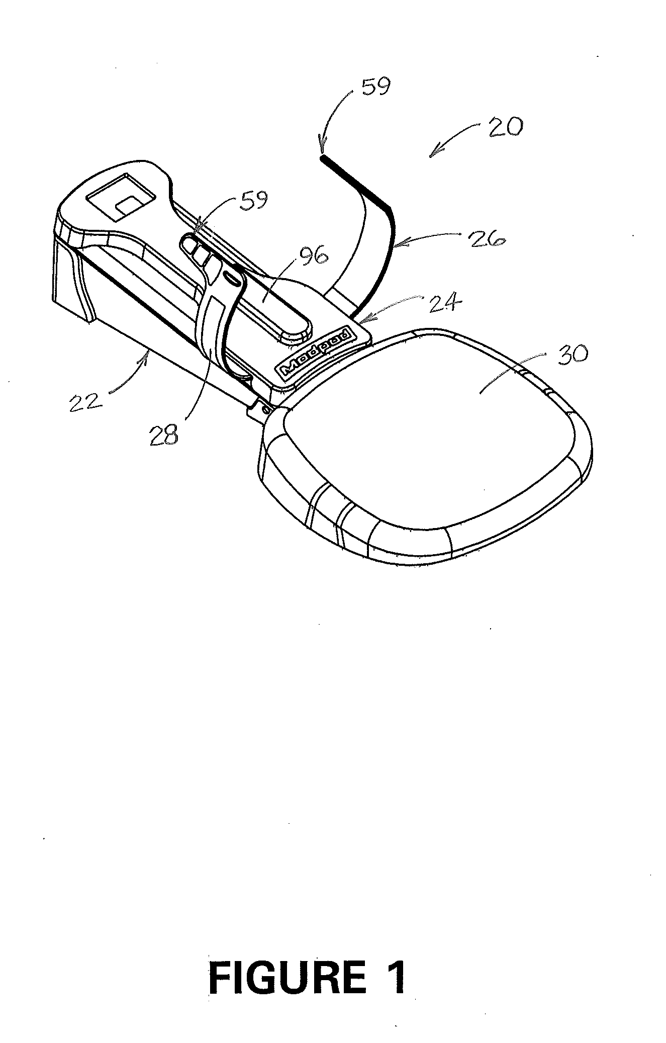
Figure 2 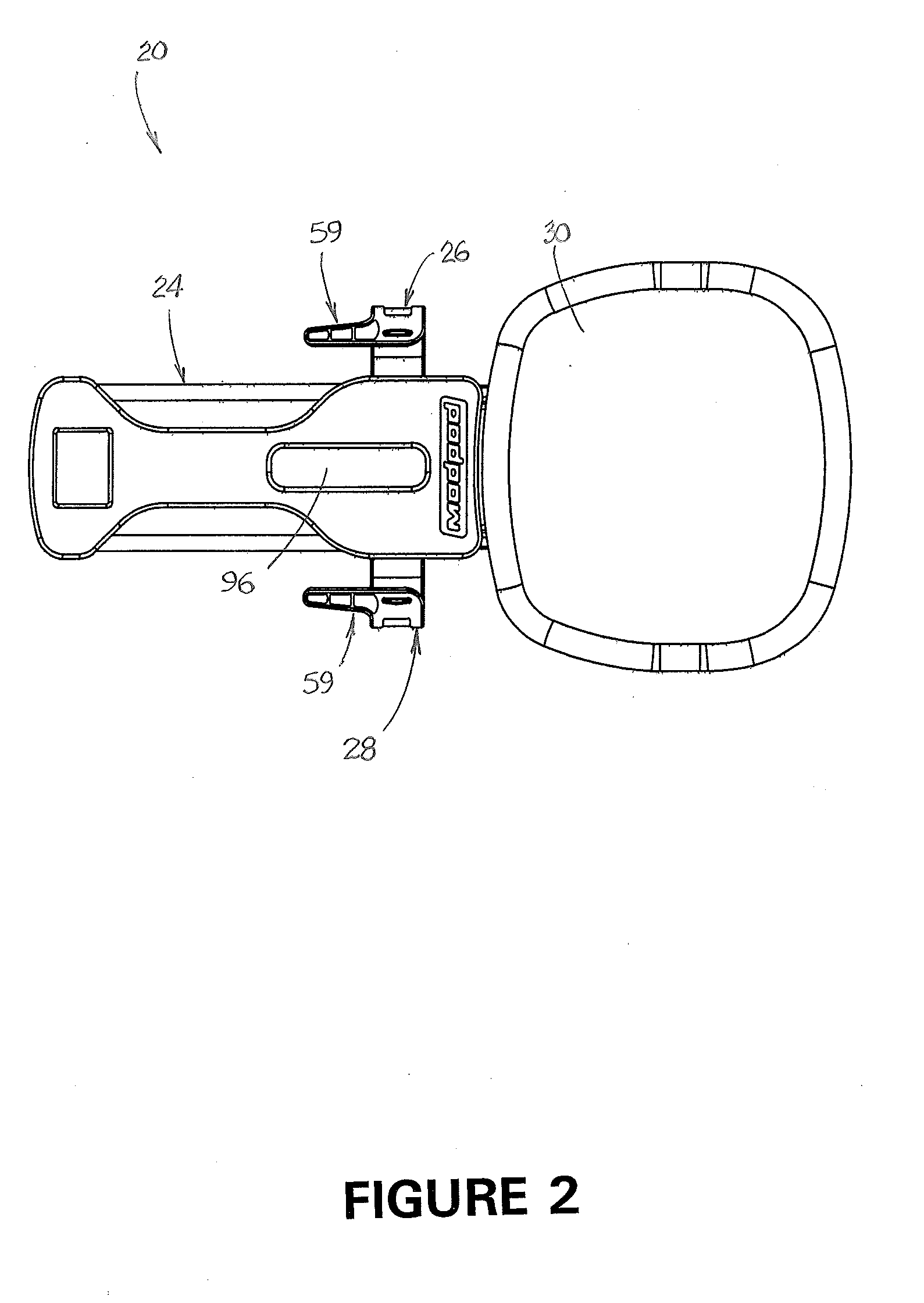
Figure 3
Abstract
Description
CROSS-REFERENCE TO RELATED APPLICATION
[0001] This application claims the benefit of U.S. Provisional Patent Application No. 62 / 025,860, which was filed on Jul. 17, 2014.FIELD OF THE INVENTION
[0002] This invention relates generally to cervical traction devices. More specifically, the invention relates to a portable cervical traction device that may be placed on any suitable surface for use in applying traction forces to the cervical musculature and spine.BACKGROUND AND DESCRIPTION OF THE PRIOR ART
[0003] Traction devices are commonly used to relieve pressure on inflamed or pinched nerves. Cervical traction devices generally operate by applying a traction force to the head and / or neck of a patient, and lumbar traction devices generally operate by applying a traction force to the lumbar spine. Such devices can relieve pain in the neck and lower back by stretching the cervical and / or lumbar musculature and spine. Generally, traction devices operate by applying a series of traction or pullin...
Examples
first embodiment
[0053]FIG. 13A is an illustration of a head halter that is a part of the preferred embodiment of the invention.
[0054]FIG. 13B is an illustration of the head halter shown in FIG. 13A, showing how it is attached to a patient and to the cervical traction device shown in FIGS. 1-6.
second embodiment
[0055]FIG. 14A is an illustration of a head halter that is a part of the preferred embodiment of the invention.
[0056]FIG. 14B is an illustration of the head halter shown in FIG. 14A, showing how it is attached to a patient and to the cervical traction device shown in FIGS. 1-6.
DESCRIPTION OF THE PREFERRED EMBODIMENT OF THE INVENTION
embodiment 20
[0057]A preferred embodiment 20 of a cervical traction device is illustrated in the drawings. As shown therein, cervical traction device 20 includes base assembly 22, sled assembly 24, left and right halter supports 26 and 28 respectively, and shoulder support cushion 30.
[0058]As shown in FIG. 6, base assembly 22 includes base frame 32, front closure 34, and sled frame 36. Two low-friction sled runners 38 are attached to the sled frame to facilitate movement of sled assembly 24 on the sled frame. Preferably, sled runners 38 are comprised of a blend of polycarbonate and glass fibers. Enclosed within base assembly 22 is linear actuator 40 (best shown in FIG. 7). Rear end 42 of linear actuator 40 is attached to load cell assembly 44 and to rear support 46 of the base assembly. Front end 48 of linear actuator 40 is attached to sled assembly 24. The load cell assembly is operatively attached to the linear actuator and to controller and interactive display assembly 49 located on controlle...