
Laser measurement system and method for measuring 21 gmes
a laser measurement system and laser technology, applied in the field of laser measurement system and method for measuring up to, to achieve the effect of improving measurement efficiency, limited measurement parameters, and limited measurement efficiency
Patent Information
- Authority / Receiving Office
- US · United States
- Patent Type
- Applications(United States)
- Current Assignee / Owner
- Publication Date
- 2017-11-02
Smart Images
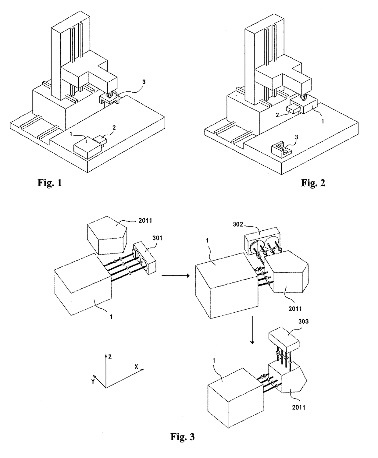
Figure 1 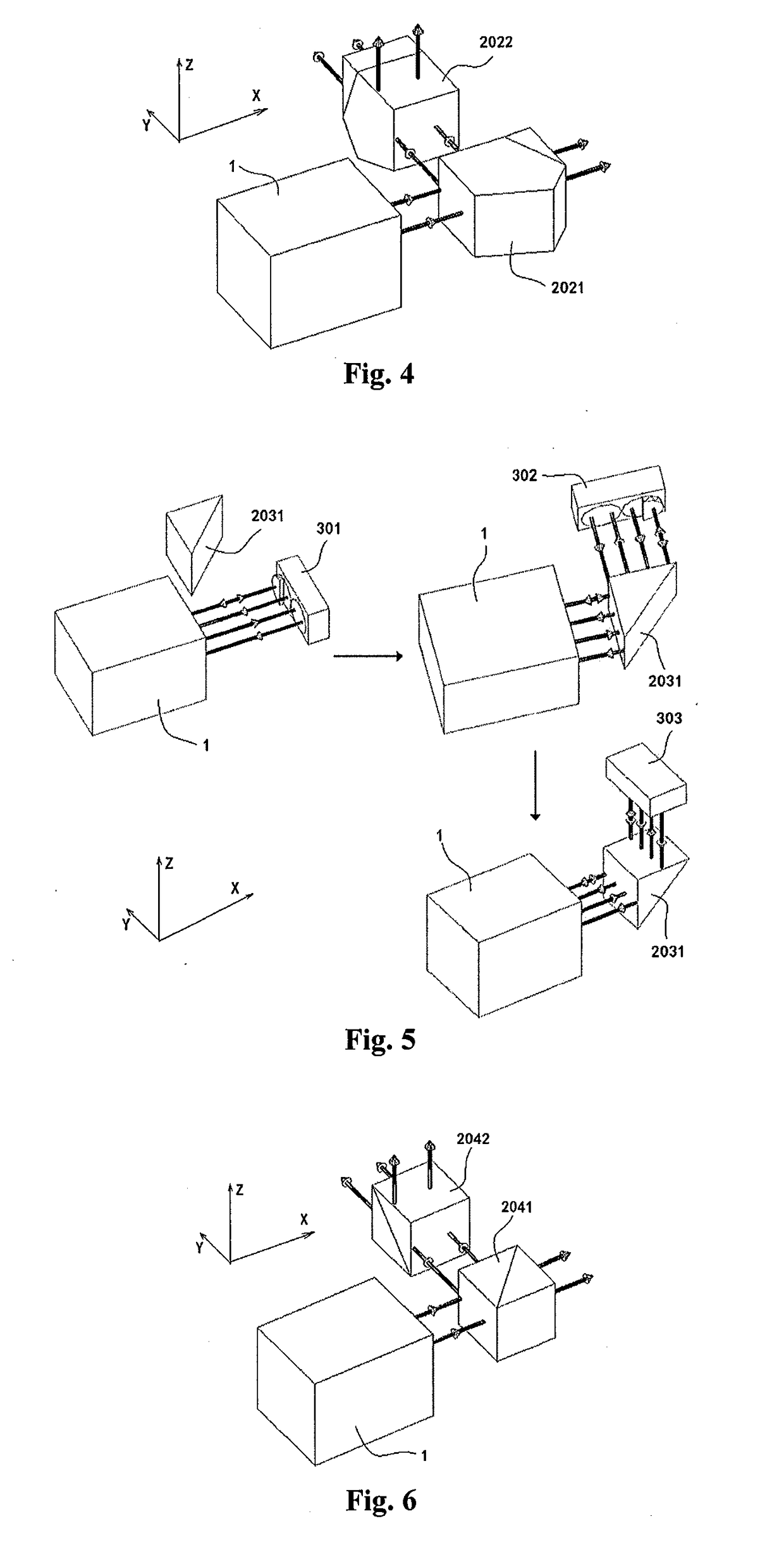
Figure 2 
Figure 3
Abstract
Description
FIELD OF THE INVENTION
[0001] The present invention relates to a laser measurement system and method for measuring up to 21 GMEs (geometric motion errors), which is used to an accuracy measurement for precise machining and measuring equipment, such as a numerical control machine tool, a machining center or a coordinate measuring machine. The field of the invention pertains to the dimensional geometric accuracy measurement, particularly to a laser measurement system and method for measuring the 21 GMEs of three mutual perpendicular linear motion guides of the equipment listed above by a single installation and step-by-step measurement.
[0002] The 21 GMEs include the 6 GMEs of the X-axis, the 6 GMEs of the Y-axis, the 6 GMEs of the Z-axis, the perpendicularity error between the X-axis and the Y-axis, the perpendicularity error between the Y-axis and the Z-axis, and the perpendicularity error between the X-axis and the Z-axis.BACKGROUND OF THE INVENTION
[0003] DE10341594A1 discloses a method...
Examples
Embodiment Construction
[0043]As shown in FIG. 1, the laser measurement system for the 21 GMEs provided by the present invention consists of the 6DOF GME simultaneous measurement unit 1, the beam-turning unit 2 and the error-sensitive unit 3. The error-sensitive unit 3 is fixed on the clamping tool of the measured numerical control machine tool, the machining center, and the coordinate measuring machine. The measurement unit 1 and the beam-turning unit 2 are mounted on the clamping workpiece of the equipment previously listed.
[0044]Referring to FIG. 2, the error-sensitive unit 3 can also be fixed on the clamping workpiece, while the measurement unit 1 and the beam-turning unit 2 can also be mounted on the clamping tool of the equipment previously listed.
[0045]As shown in FIG. 3, the pentagonal prism 2011 is used in the beam turning 2 to turn the laser beam from the measurement unit 1. The pentagonal prism 2011 is removed from the light path of measurement unit 1 by manual or electro-kinetic operation. The ...