
Remote device and remote device system
a remote device and remote control technology, applied in the field of remote devices and remote control systems, can solve the problems that the light received through a single aperture may not be able to ensure a distance, and achieve the effect of improving the light-reception sensitivity of optical remote controls
Patent Information
- Authority / Receiving Office
- US · United States
- Patent Type
- Applications(United States)
- Current Assignee / Owner
- Publication Date
- 2018-08-16
Smart Images
Figure 1 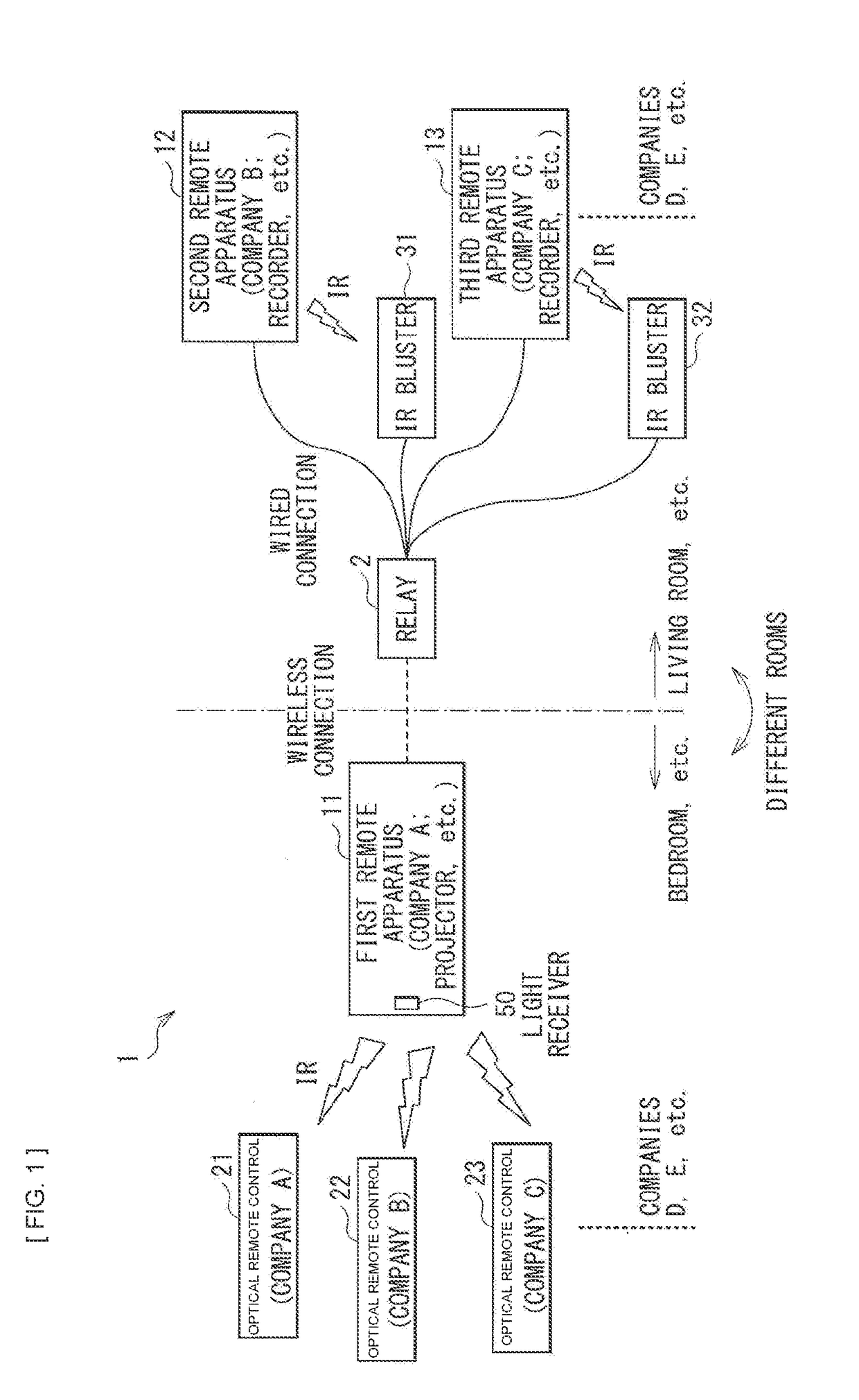
Figure 2 
Figure 3
Abstract
Description
TECHNICAL FIELD
[0001] The disclosure relates to a remote device and a remote device system that are both operable with optical remote controls (remote controller).BACKGROUND ART
[0002] An optical remote device system using infrared rays includes: an optical remote control; and a device main body that is operable with this remote control. The remote control is provided with a light emitting body that emits infrared rays as signal light. The device main body is provided with a light receiver that receives the signal light. There are cases where the light receiver is provided inside the exterior of the device main body or another structure. As an example, PTL 1 proposes a technique in which a light receiver is provided inside the exterior. As another example, PTL 2 proposes a technique in which a light receiver is provided inside a speaker grille with punched holes.CITATION LISTPatent Literature
[0003] [PTL 1] Japanese Unexamined Patent Application Publication No. 2004-320304
[0004] [PTL 2] J...
Examples
first embodiment (a remote device that includes a reflecting structure as a light guiding section) (figs.1 to 20)
1. First embodiment (a remote device that includes a reflecting structure as a light guiding section) (FIGS. 1 to 20)
[0039]1. 1 Outline of remote device system
[0040]1. 2 Exterior and inner configuration examples of remote device
[0041]1. 3 Effects
second embodiment (a remote device that includes an on-axis optical member and a wide-angle optical member as a light guiding section) (figs.21 to 26)
2. Second embodiment (a remote device that includes an on-axis optical member and a wide-angle optical member as a light guiding section) (FIGS. 21 to 26)
3. Other embodiments
first embodiment
1. First Embodiment
1. 1 Outline of Remote Device System
[0042]An optical remote device system includes: an optical remote control; and a device main body that is operable with this optical remote control. The optical remote control is provided with a light emitting body that emits infrared rays as signal light. The device main body is provided with a light receiver having a light receiving sensor that receives the signal light.
[0043]Pieces of carrier light to be emitted are modulated, so that remote control signals are assigned to respective optical remote controls. In general, company products employ different carrier frequencies, as an example listed below.
[0044]Company A: 38 kHz
[0045]Company B: 40 kHz
[0046]Company C: 36 kHz
[0047]Company D: 30 kHz
[0048]A typical product includes a product-dedicated optical remote control and a product-dedicated light receiving sensor. The optical remote control and the light receiving sensor employ a one-to-one configuration. Thus, the light receiv...