
Expandable and adjustable lordosis interbody fusion system
Patent Information
- Authority / Receiving Office
- US · United States
- Current Assignee / Owner
- Publication Date
- 2020-03-12
Smart Images
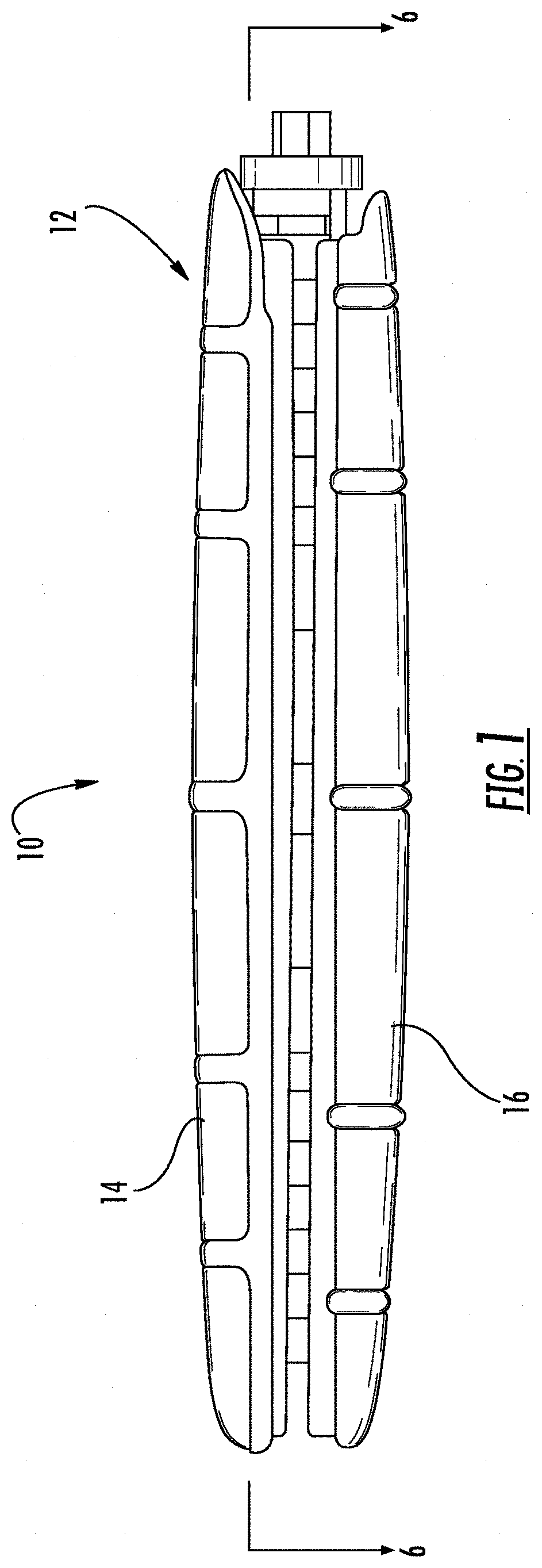
Figure 1 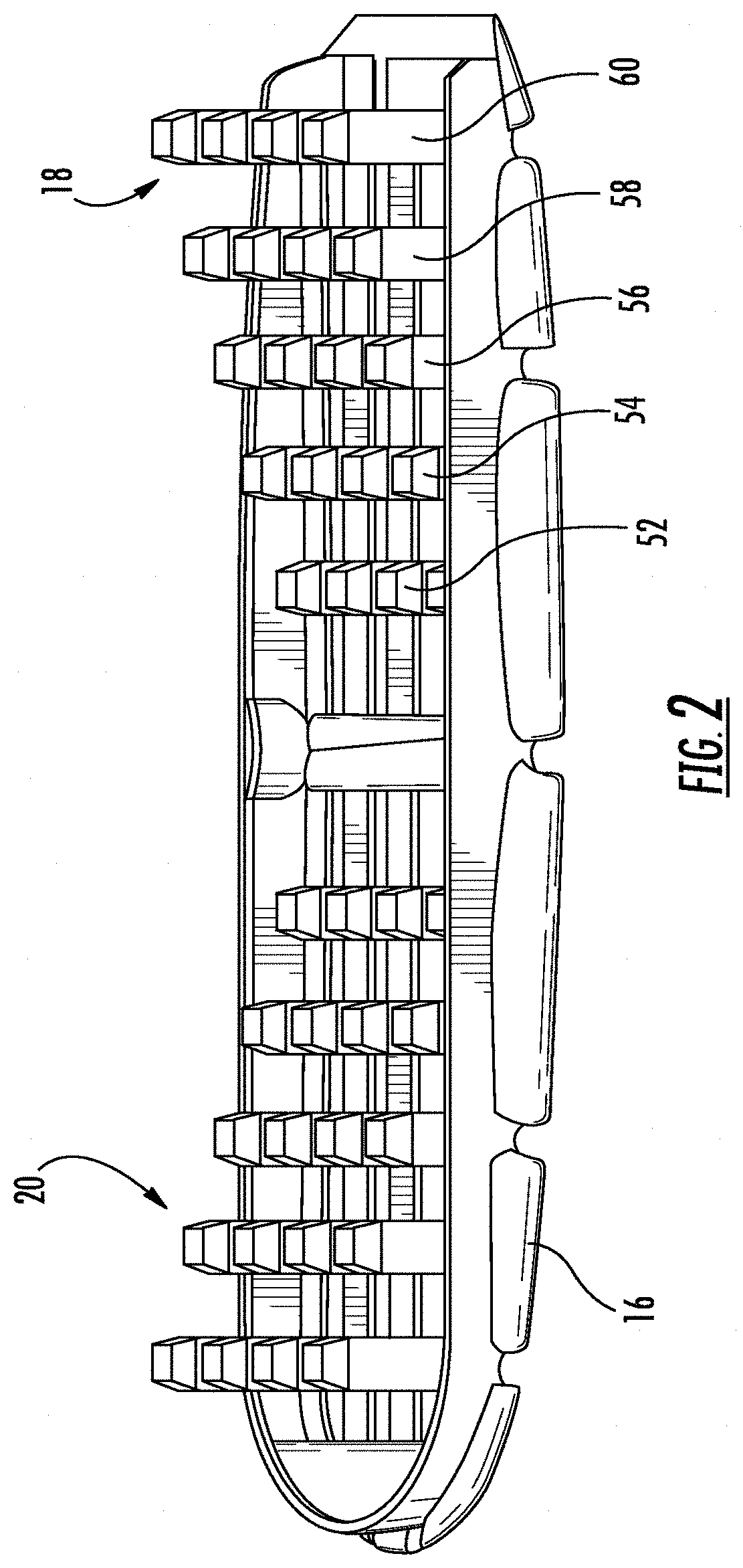
Figure 2 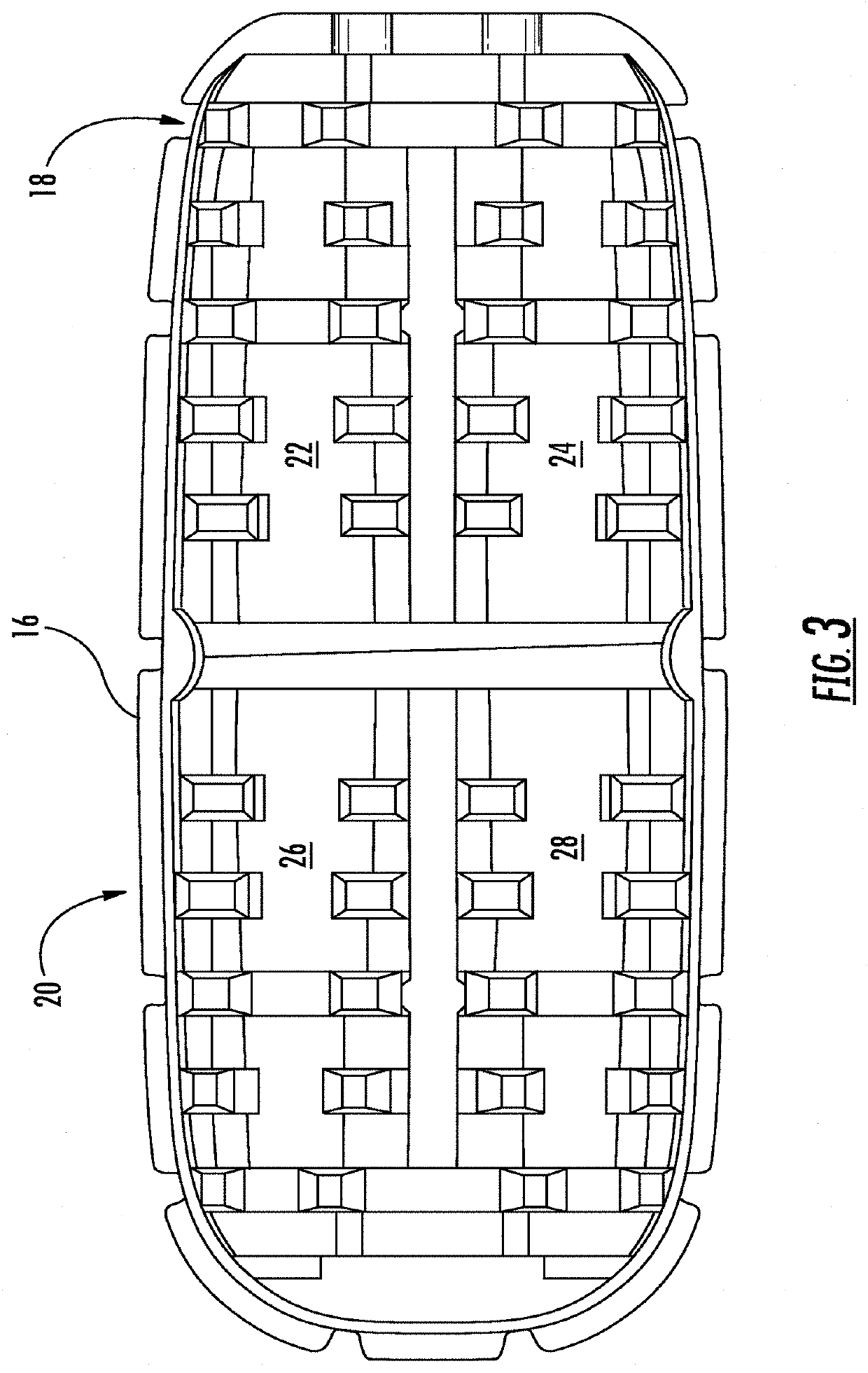
Figure 3
Abstract
Description
RELATED APPLICATIONS
[0001] This application is a continuation-in-part of U.S. application Ser. No. 16 / 001,852 filed Jun. 6, 2018 entitled “EXPANDABLE AND ADJUSTABLE LORDOSIS INTERBODY FUSION SYSTEM,” which is a continuation of U.S. application Ser. No. 15 / 859,241 filed Dec. 29, 2017 entitled “EXPANDABLE AND ADJUSTABLE LORDOSIS INTERBODY FUSION SYSTEM,” issued as U.S. Pat. No. 10,188,527 on Jan. 29, 2019, which is a continuation of Ser. No. 14 / 473,200 filed Aug. 29, 2014 entitled “EXPANDABLE AND ADJUSTABLE LORDOSIS INTERBODY FUSION SYSTEM,” issued as U.S. Pat. No. 9,889,019 on Feb. 13, 2018, which claims priority to U.S. provisional patent application No. 61 / 871,780 filed Aug. 29, 2013 entitled “EXPANDABLE LATERAL INTERBODY FUSION SYSTEM,” the disclosures of all of which are hereby incorporated by reference in their entirety.
[0002] This application claims priority to U.S. provisional patent application No. 62 / 736,649 filed Sep. 26, 2018 entitled “EXPANDABLE AND ADJUSTABLE LORDOSIS INTE...
Examples
Embodiment Construction
.
BRIEF DESCRIPTION OF THE DRAWINGS FIGURES
[0017]An embodiment of the present invention is described herein with reference to the following drawing figures, with greater emphasis being placed on clarity rather than scale:
[0018]FIG. 1 is a view in side elevation from the side of the expandable shell device.
[0019]FIG. 2 is a perspective view of a bottom section of the expandable shell.
[0020]FIG. 3 is a top plan view of the bottom section of the expandable shell.
[0021]FIG. 4 is a top plan view of the expandable shell device.
[0022]FIG. 5 is a perspective view of a tapered external helical threaded member.
[0023]FIG. 5A is a view in side elevation from the side of the tapered external helical threaded member.
[0024]FIG. 5B is a view in side elevation from the front of the tapered external helical threaded member.
[0025]FIG. 6 is a cross-sectional view of the device taken along lines 6-6 in
[0026]FIG. 1.
[0027]FIGS. 7A-7C are a series of views in side elevation of the device as it undergoes exp...