
Stacked connector
Patent Information
- Authority / Receiving Office
- US · United States
- Current Assignee / Owner
- Publication Date
- 2020-04-30
Smart Images
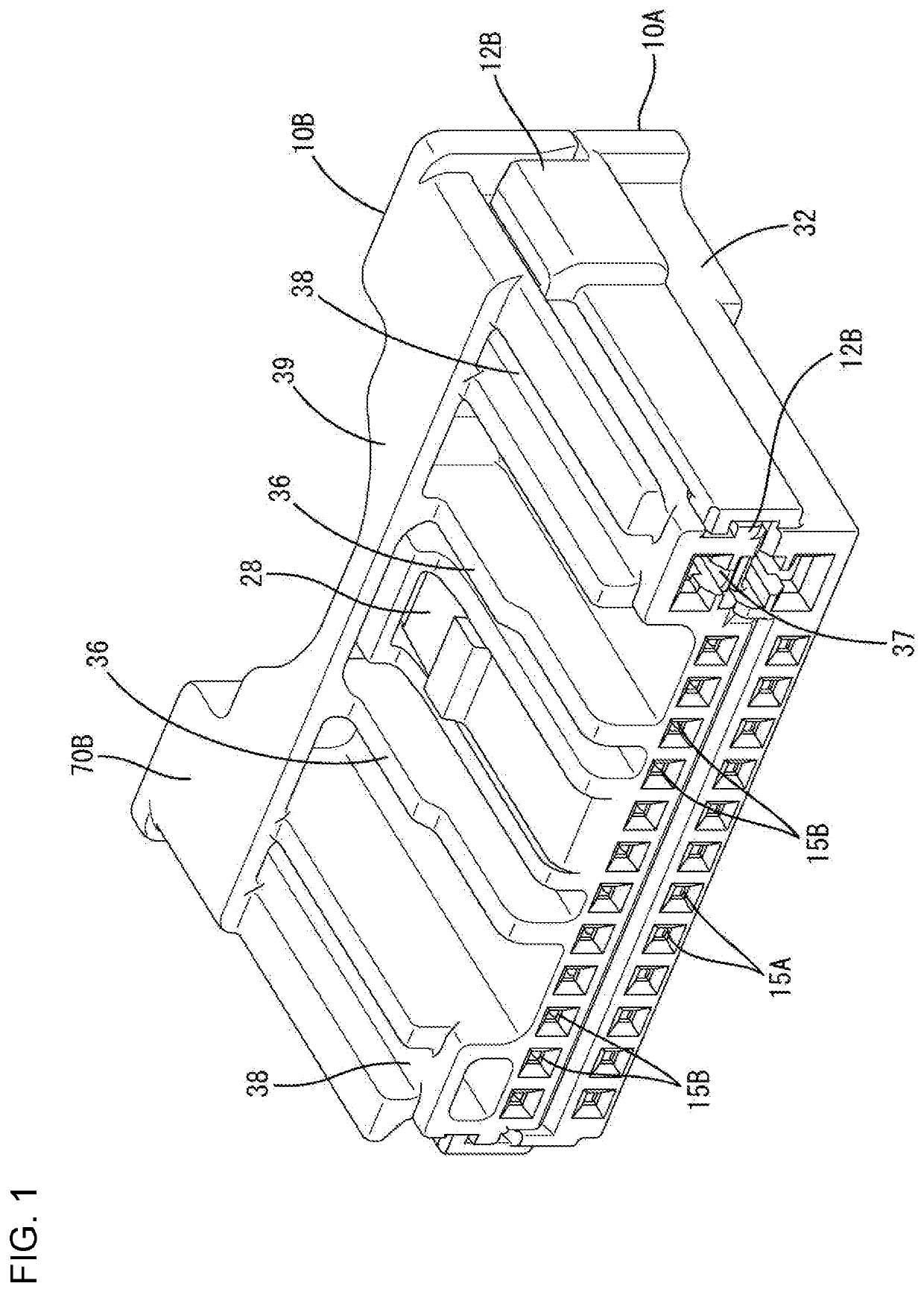
Figure 1 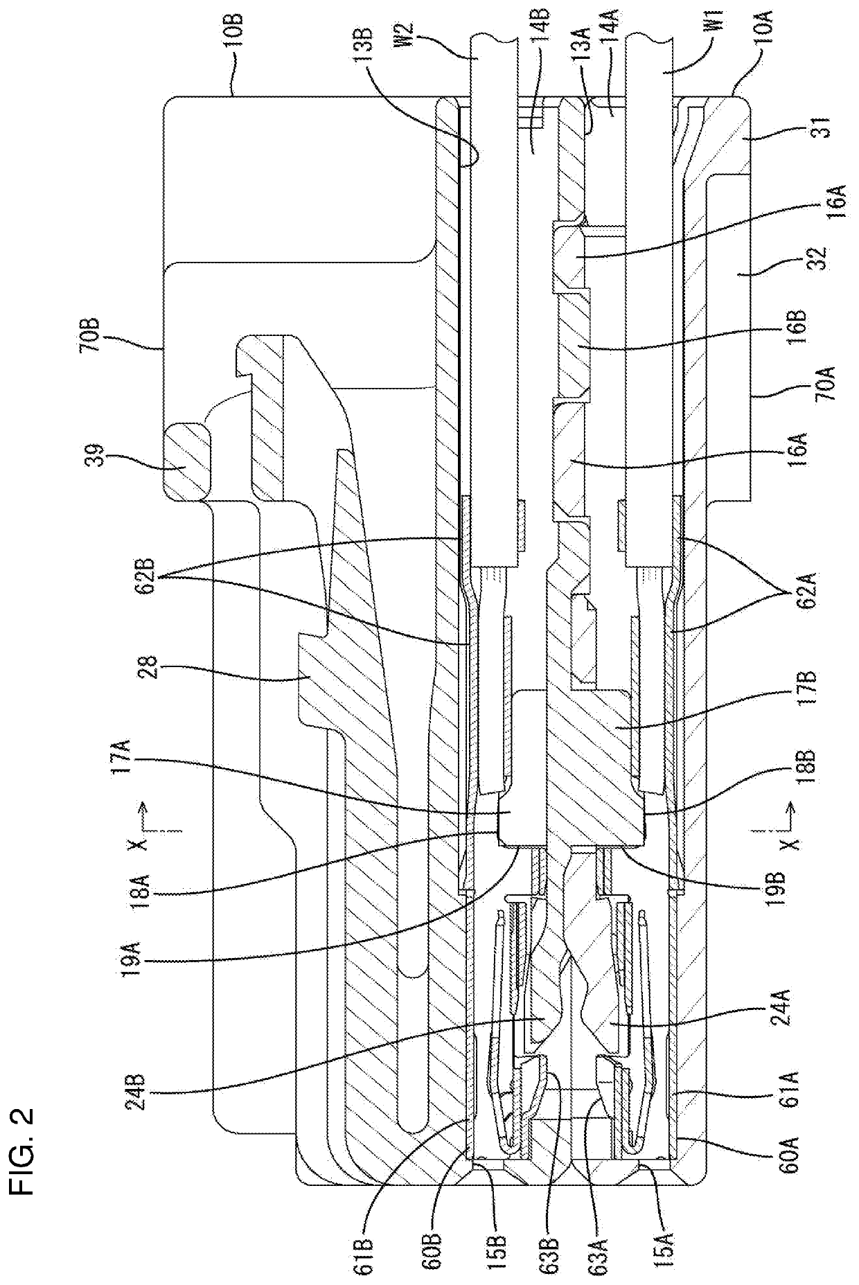
Figure 2 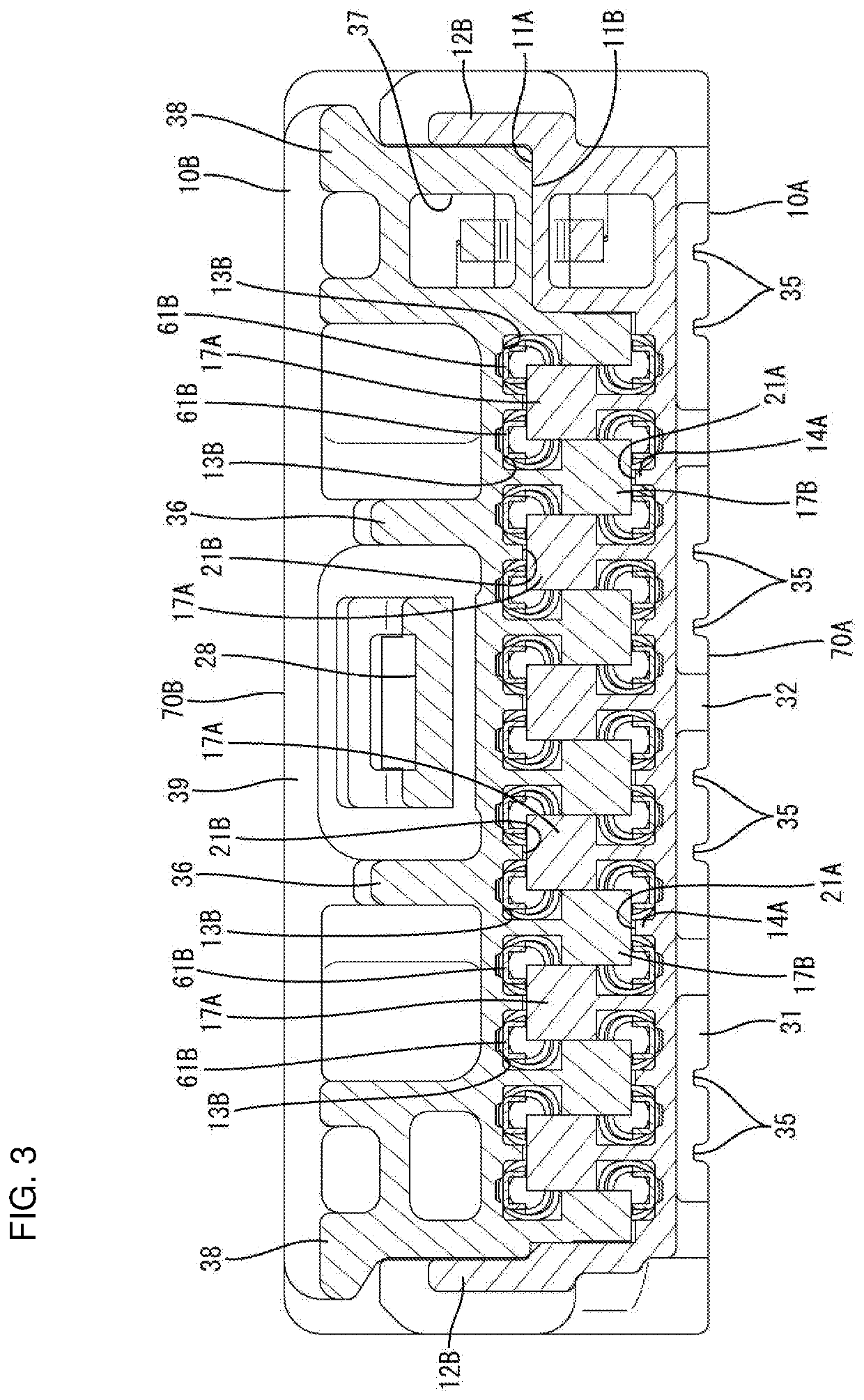
Figure 3
Abstract
Description
BACKGROUNDField of the Invention
[0001] The invention relates to a stacked connector.Related Art
[0002] Japanese Unexamined Patent Publication No. 2006-294580 discloses a connector with two housings to be stacked on and united with each other. Connector housing locking means are disposed on both end parts in a width direction intersecting a stacking direction and are configured for holding the connector housings in a united state. Detecting portions project from a facing surface of one connector housing facing a facing surface of the other connector housing and interfere with terminal fittings accommodated in the other connector housing to detect an incompletely inserted state of the terminal fittings.
[0003] Interference of the detecting portion of the one connector housing with the incompletely inserted terminal fitting restricts the entrance of the detecting portion into the other connector housing. Thus, a clearance is formed between the facing surfaces of the connector housings at a ...
Examples
Embodiment Construction
[0020]An embodiment is described with reference to FIGS. 1 to 9. A stacked connector of this embodiment includes a first housing 10A and a second housing 10B to be stacked one on the other. First terminal fittings 60A and second terminal fittings 60B are to be accommodated respectively into the first and second housings 10A, 10B. In the following description, a left side of FIGS. 2 and 4 is referred to as a front concerning a front-rear direction and a vertical direction is based on a vertical direction of the figures except FIG. 7.
[0021]The first housing 10A is a lower housing and, as shown in FIG. 6, has a flat shape with a width direction intersecting a vertical direction (stacking direction) as a longitudinal direction and has a first facing surface 11A facing the second housing 10B as a stacking partner on an upper surface. The first housing 10A includes first housing locks 12A in the form of plates extending along the front-rear direction on both widthwise sides.
[0022]The firs...