
Connector and manufacturing method therefor
a manufacturing method and connector technology, applied in the field of connectors, can solve the problems of complex structure of the lower mold for insert molding, lid needs to be covered with resin, cannot be supported by the upper mold, etc., to achieve simple structure, high accuracy, and not complicated mold structure
Patent Information
- Authority / Receiving Office
- US · United States
- Patent Type
- Applications(United States)
- Current Assignee / Owner
- Publication Date
- 2020-11-05
Smart Images
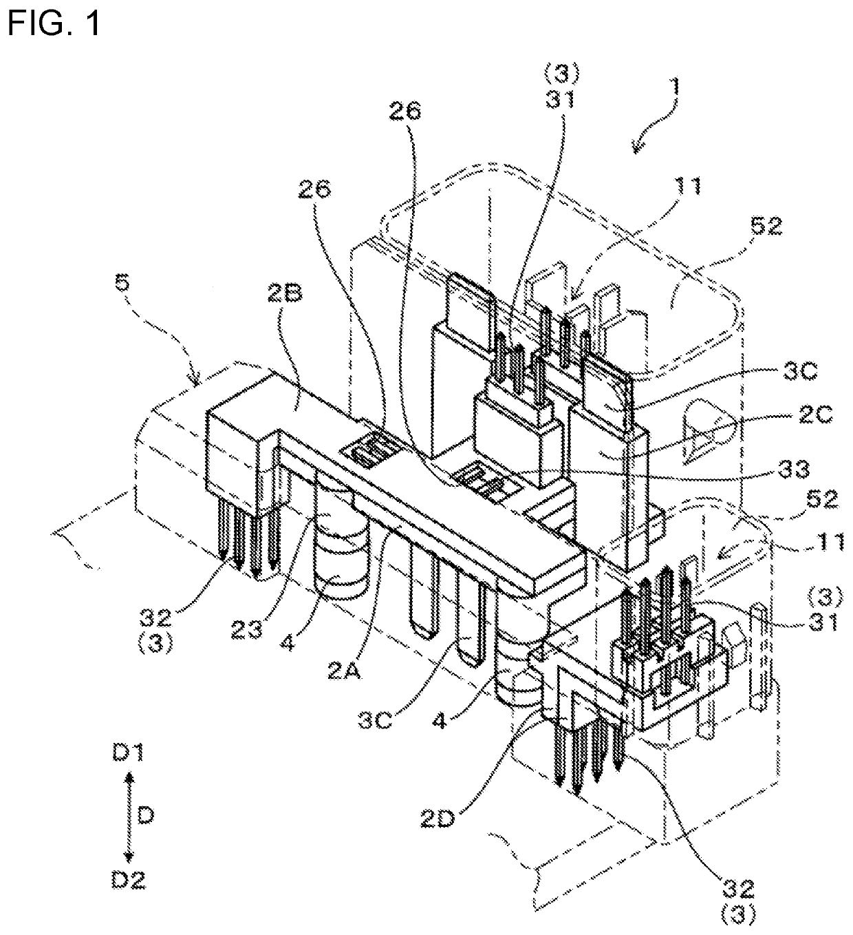
Figure 1 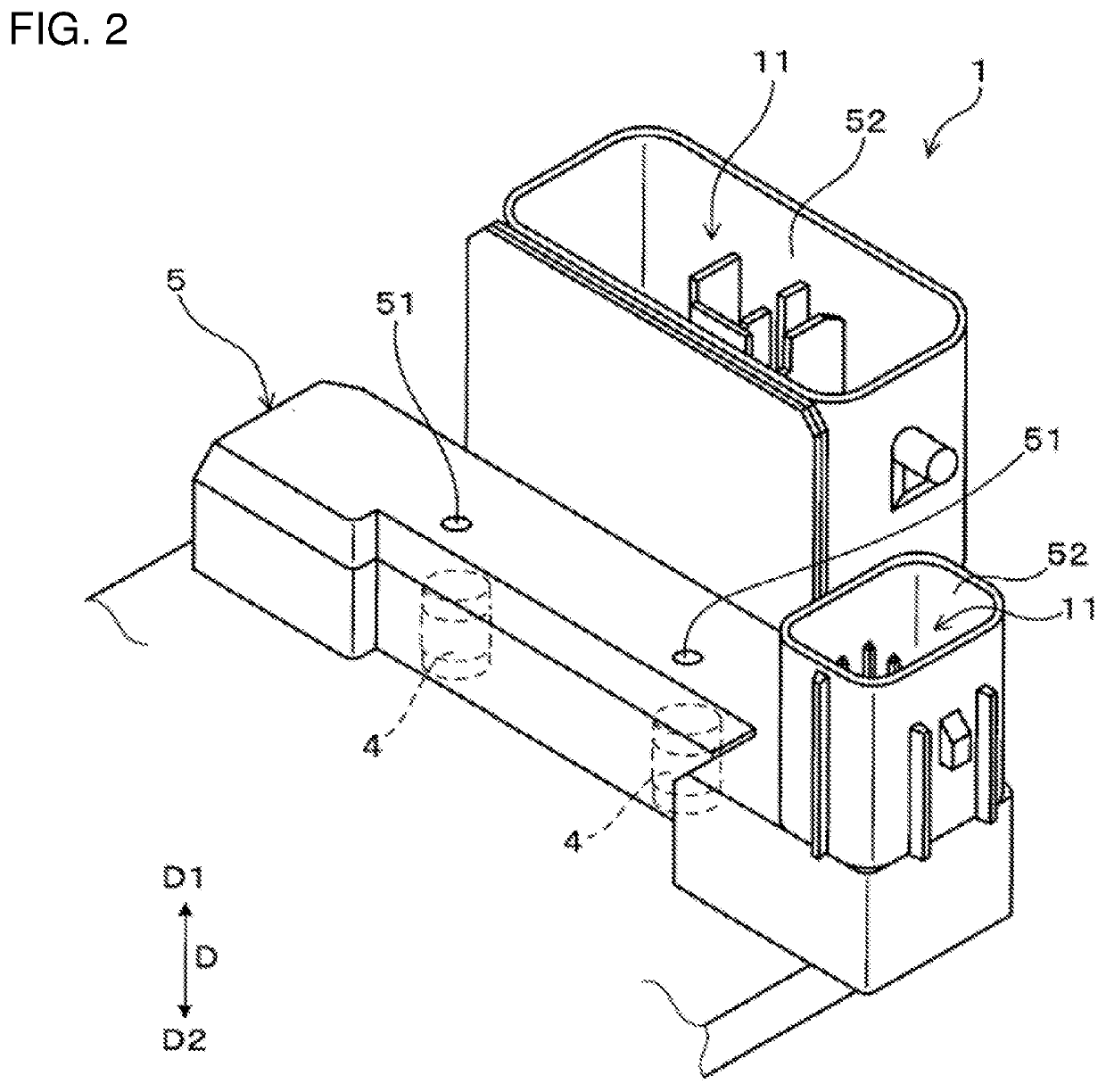
Figure 2 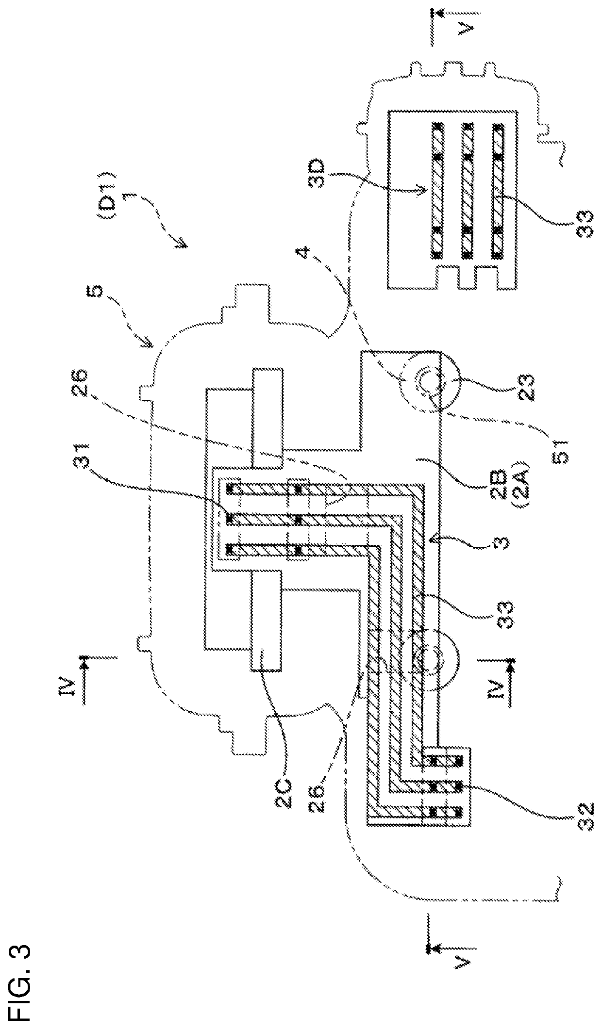
Figure 3
Abstract
Description
BACKGROUNDField of the Invention
[0001] The invention relates to a connector including a plurality of connector terminals and a manufacturing method therefor.Related Art
[0002] A connector provided with connector terminals is used in wiring an electronic control component and a control device in various machine components. The connector terminals may be arranged in a connector case made of resin by performing insert molding. Further, a nut for mounting the connector on various mounting components may be arranged in the connector case by performing insert molding.
[0003] Japanese Unexamined Patent Publication No. 2017-105150 discloses an insert molded article and a manufacturing method where a through nut and a lid are covered by insert molding of resin so that a first opening of the through nut is closed by the lid and a second opening of the through nut is exposed to outside. In performing the insert molding, an inner peripheral side of the second opening of the through nut is fit to a p...
Examples
first embodiment
[0037]A connector 1 of this embodiment includes connector terminals 3, core resin portions 2A, 2B, nuts 4 and an outer resin portion 5, as shown in FIGS. 1 to 5. The connector terminals 3 are conductive conductors. Both end parts 31, 32 of the connector terminals 3 project from the core resin portions 2A, 2B, and intermediate parts 33 of the connector terminals 3 (except the both end parts 31, 32) are embedded in the core resin portions 2A, 2B.
[0038]As shown in FIGS. 1, 4 and 5, the nuts 4 are arranged to face a nut facing surface 21A of the core resin portion 2A. Each nut 4 includes a screw hole 40 extending from an outer end surface 41 located on a side opposite to a side facing the nut facing surface 21A. The outer resin portion 5 covers the core resin portions 2A, 2B and the nuts 4 with exposed surfaces 25 as parts of the core resin portions 2A, 2B and the outer end surfaces 41 of the nuts 4 exposed. Injection marks 51 made during the molding of the outer resin portion 5 are for...
second embodiment
[0090]In a connector 1 of this embodiment, through holes 27 to be filled by an outer resin portion 5 are formed in a first core resin portion 2A and a second core resin portion 2B as shown in FIGS. 13 and 14 to more reliably maintain nuts 4 in specified postures.
[0091]As shown in FIGS. 13 and 14, the through holes 27 penetrating toward the nuts 4 are formed in parts of the first and second core resin portions 2A, 2B of this embodiment facing the nuts 4. The through holes 27 of the first core resin portion 2A penetrate from nut facing surfaces 21A of facing projections 23 to an opposite side surface 22A. The through holes 27 of the second core resin portion 2B penetrate at positions facing the through holes 27 of the first core resin portion 2A.
[0092]The outer resin portion 5 is filled continuously into the through holes 27 of the first core resin portion 2A and those of the second core resin portion 2B. Further, injection marks 51 of this embodiment are formed on a surface of a part...