
Mechanism capable of realizing two times of core pulling and forcible hole stripping operation by virtue of slide
A technology of slider 2 and slider, which is applied in the field of slider secondary core-pulling and strong hole removal mechanism, can solve problems such as the overall structure of the mold, and achieve the effects of reducing the configuration of the mold mechanism, reducing the volume of the mold, and simplifying the structure of the mold
Patent Information
- Authority / Receiving Office
- CN · China
- Current Assignee / Owner
- Publication Date
- 2017-08-18
Smart Images
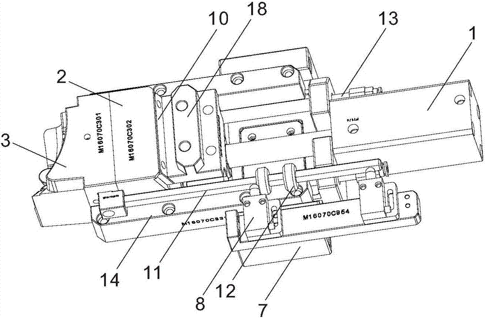
Figure 1 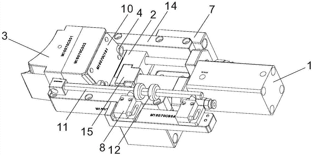
Figure 2 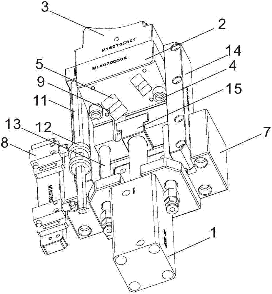
Figure 3
Abstract
Description
technical field
[0001] The invention relates to a mold working mechanism, more specifically, it relates to a sliding block secondary core-pulling and strong hole-removing mechanism. Background technique
[0002] Many injection molding products have U-shaped buckles with inner undercut structures. The processing method of directly forming the inner undercut structure by melting the material is the most ideal. The inner undercut structure generated in this way is smooth and continuous, with good consistency, complete structure and high strength. High, but one of the biggest difficulties in implementing this processing method is that when the mold is opened, the step structure of the forming hole of the U-shaped buckle and the inner undercut structure on the mold has formed a bite with the cured rubber, and when the mold is opened, generally only a simple Move in a straight line, so the U-shaped buckle of the injection molded product cannot be separated from the forming hole on...
Examples
Embodiment
[0029] Such as Figure 1 to Figure 10As shown, a slider secondary core-pulling strong hole removal mechanism is set on the mold. The slider secondary core-pulling strong hole removal mechanism includes an oil cylinder 1, a slider body 2, a slider head 3, and a threaded limit sleeve 4. The outer pin 5 of the U-shaped buckle and the center pin 6 of the U-shaped buckle that can be extended to the mold core, the piston rod of the oil cylinder 1 is connected with the slider body 2, and the slider body 2 and the slider head 3 are slid and connected to each other. On a pair of parallel guide rods 13, the guide rods 13 are fixed on a base frame 7, so that the slider body 2 and the slider head 3 are slidably connected with the base frame 7. The outer pins 5 of the U-shaped buckle are fixed on the slider body 2 and slide through the slider head 3. The outer pins 5 of the U-shaped buckle are arranged in pairs, and there are two pairs in total. The central pin 6 of the U-shaped buckle is ...