
Twisting mold of fat steel and flat steel twisting method
A flat steel and mold technology, applied in the field of flat steel torsion molds and torsion flat steel, can solve the problems of inability to guarantee the precision of torsion forming, high artificial torsion strength, material damage, etc. It is easy to guarantee the torsion accuracy, and the production continuity is good. The effect of high accuracy of torsion molding
Patent Information
- Authority / Receiving Office
- CN · China
- Current Assignee / Owner
- Publication Date
- 2014-01-01
- Estimated Expiration
- Not applicable · inactive patent
Smart Images
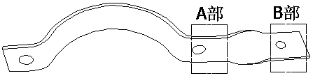
Figure 1 
Figure 2 
Figure 3
Abstract
Description
technical field
[0001] The invention relates to a flat steel torsion mold and a method for torsion flat steel. Background technique
[0002] A commonly used connector on a transmission tower, such as figure 1 As shown, it is made by bending flat steel. Due to connection requirements, part B must be twisted 90 degrees relative to part A. o , so that the surface of part B is perpendicular to the surface of part A.
[0003] The method for realizing the twisting of the above-mentioned angle steel usually adopts oxy-acetylene flame heating or heating in a heating furnace, and after reaching a certain temperature, twisting is manually performed by using simple tools. The disadvantages of this processing method are as follows:
[0004] (1) The heated joints are manually twisted and formed, which has high working strength, low processing efficiency, large dust in the working environment, and serious harm to the workers' bodies;
[0005] (2) Partial heating of the connecting part...
Examples
Embodiment Construction
[0029] An embodiment of the present invention will be further described in detail below in conjunction with the accompanying drawings and specific implementation methods.
[0030] A kind of flat steel torsion die of the present embodiment, as Figure 2-4 As shown, it includes base 1, support one 2, support two 3 and rotating block 4, wherein support one 2, support two 3 are fixedly arranged on the upper surface of base 1 and support one 2, support two 3 Relatively arranged, and the rotating block 4 is located between the support one 2 and the support two 3, the rotating block 4 is rotatably connected with the support one 2, and also includes a rotary drive device for driving the rotating block 4 relative to the support one 2 rotate. In the initial state, the upper surface 41 of the rotating block 4 is parallel to the upper surface of the base 1 , and the front surface 42 of the rotating block 4 is perpendicular to the upper surface 41 . And the rotating block 4 is provided w...