
Ultraviolet sterilization device
a sterilization device and ultraviolet light technology, applied in the direction of multi-stage water/sewage treatment, instruments, separation processes, etc., can solve the problems of reducing the efficacy of the device, reducing transmission, and affecting the efficiency of the device, so as to enhance the efficiency and consistency of the apparatus, improve the effect of effectiveness and increase light penetration
Patent Information
- Authority / Receiving Office
- US · United States
- Patent Type
- Patents(United States)
- Current Assignee / Owner
- Publication Date
- 2006-04-18
- Estimated Expiration
- Not applicable · inactive patent
Smart Images
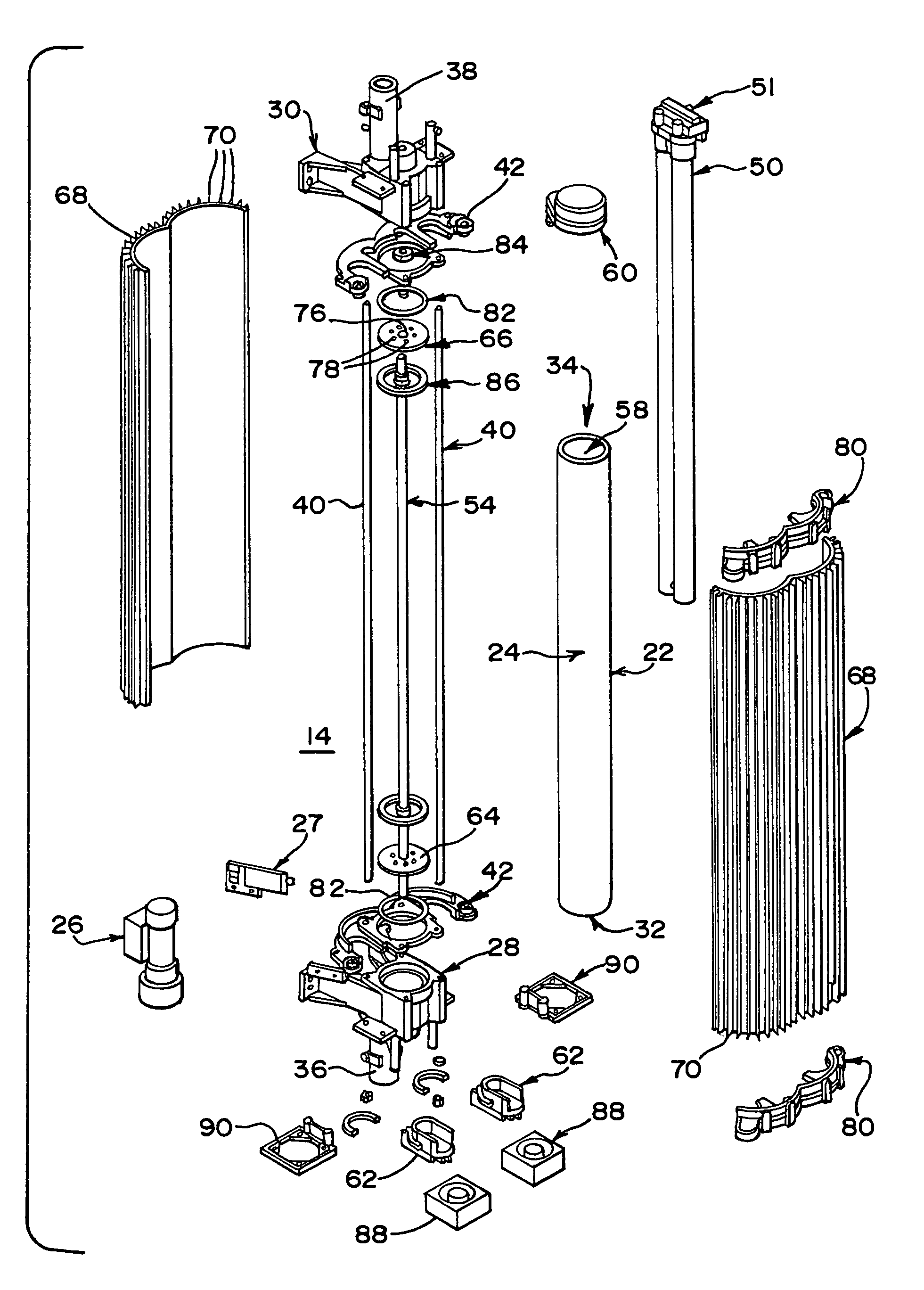
Figure 1 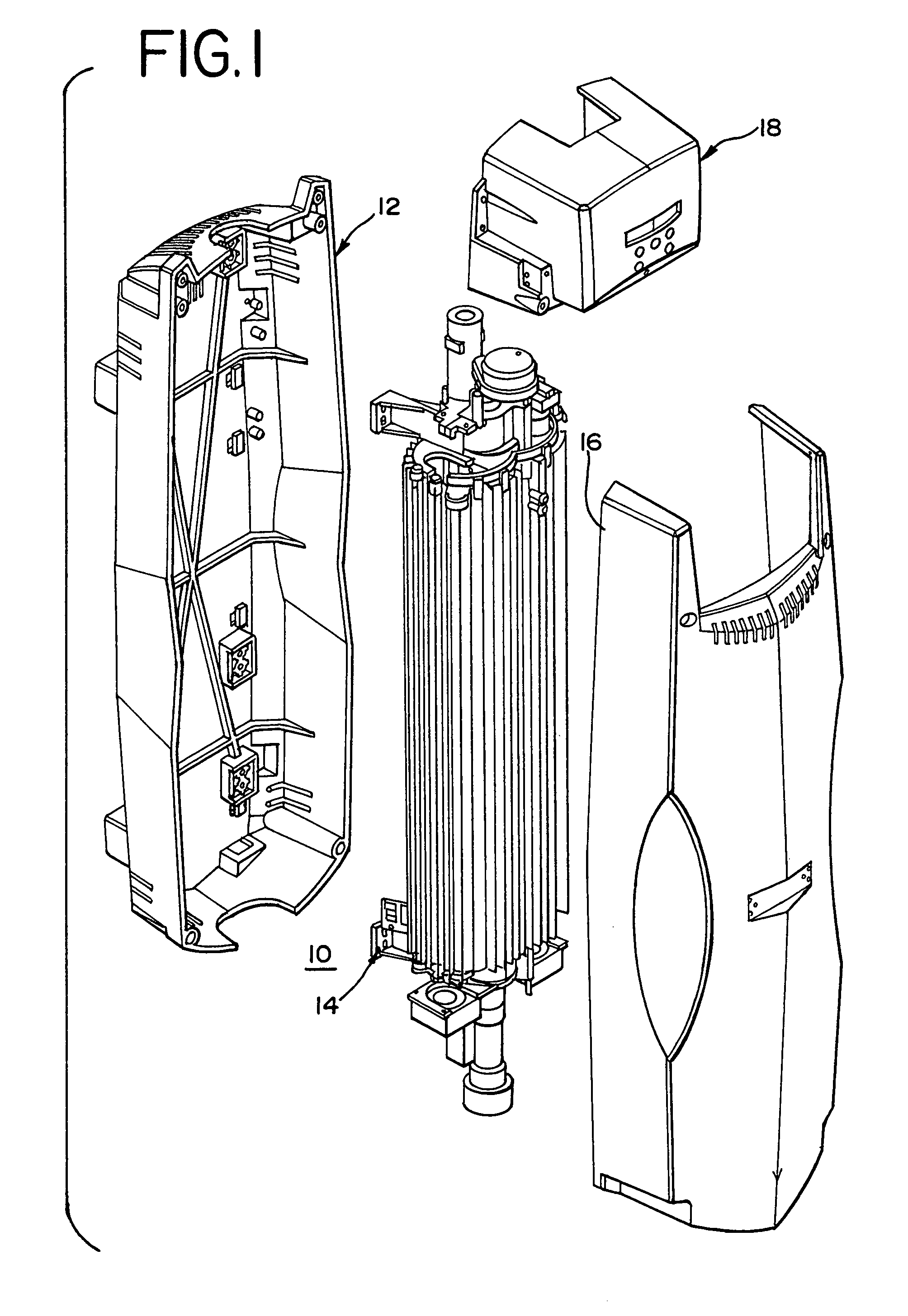
Figure 2 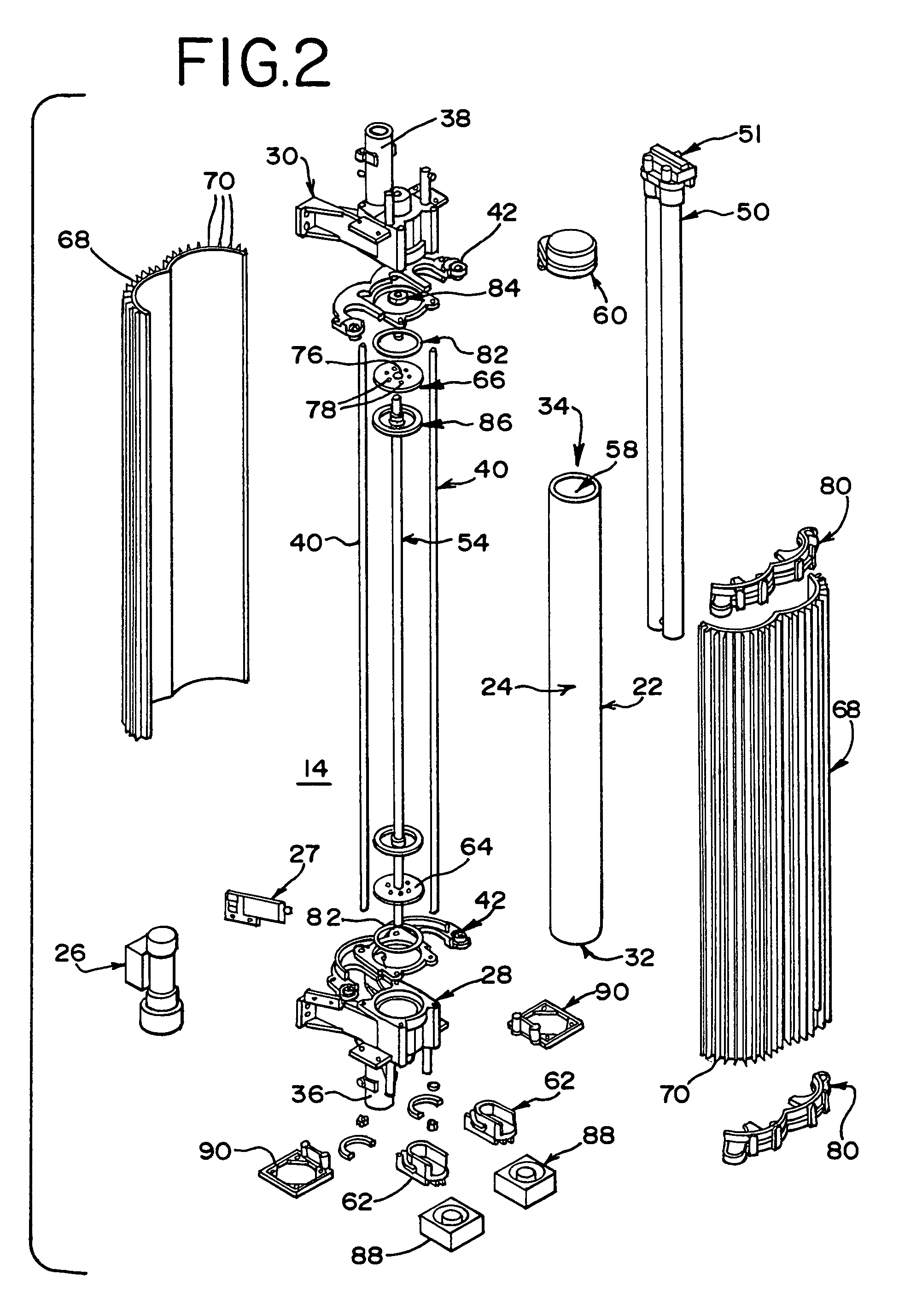
Figure 3
Abstract
Description
FIELD OF THE INVENTION
[0001] This invention relates to an apparatus for subjecting fluids to ultraviolet (UV) light. The apparatus may be used for water sterilization and is intended for Point-of-Entry use.BACKGROUND OF THE INVENTION
[0002] Point-of-Entry ultraviolet water sterilization devices typically include a pressure vessel including a stainless steel cylinder enclosing a smaller concentric quartz light transmission tube. Within the quartz tube is a tubular discharge lamp emitting light with wavelengths typically centered around 254 nm, which is referred to as ultraviolet light or ultraviolet radiation. Ultraviolet (UV) light represents a section of the overall electromagnetic spectrum of light, extending from the blue end of the visible at about 400 nm to a region of about 100 nm.
[0003] Water to be exposed to the light from the lamp is passed between the interior surface of the steel cylinder and the exterior surface of the light transmission tube. One important limitation to thi...
Examples
Embodiment Construction
[0023]FIG. 1 illustrates one embodiment of subassemblies of an apparatus 10 according to the present invention. A back body housing 12 defines a chamber in which a UV chamber subassembly 14 is positioned. A front body cover 16, when fastened to the back body housing 12 effectively encloses the UV chamber subassembly 14. An electronic subassembly 18 fastens to an upper end of the back and front body covers 12, 16. It will be understood that reasonably different arrangements which function in an equivalent fashion and different appearances of the subassemblies are contemplated by the present invention. Furthermore, it will be understood that it is considered within the current state of the art for one to design appropriate circuitry to provide the functionality of the apparatus of the present invention.
[0024]An embodiment of the UV chamber subassembly 14 according to the present invention is illustrated in FIG. 2. It will be understood that the elements of the subassembly 14, describe...