
Nonaqueous electrolyte battery
a technology of electrolyte battery and non-aqueous electrolyte, which is applied in the direction of non-aqueous electrolyte cells, cell components, electrochemical generators, etc., can solve the problems of inconvenient variation of character and difficulty in and achieve the effect of widening the selection range of electrolytes
Patent Information
- Authority / Receiving Office
- US · United States
- Patent Type
- Patents(United States)
- Current Assignee / Owner
- Publication Date
- 2008-06-03
Smart Images
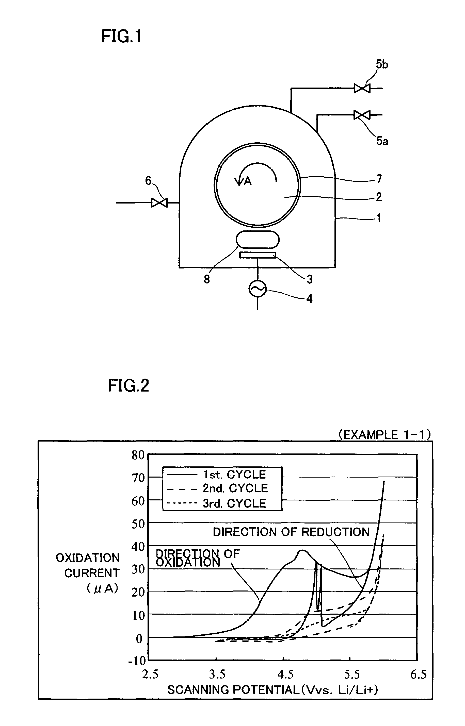
Figure 1 
Figure 2 
Figure 3
Abstract
Description
[0001] This application is a continuation of international application PCT / JP03 / 014093 filed on Nov. 5, 2003.TECHNICAL FIELD
[0002] The present invention relates to a nonaqueous electrolyte battery, and more particularly, it relates to a nonaqueous electrolyte battery having a collector.BACKGROUND TECHNIQUE
[0003] In general, researches on an electrode active material, an electrolyte, a separator and a collector etc. are carried out as researches related to a nonaqueous electrolyte battery. Among these, many researches are carried out on the electrode active material, the electrolyte and the separator. In relation to the collector, the researches remain remarkably extremely partial since the material constituting the collector is limited to a metal or a semimetal due to the basic property that the collector must efficiently collect electricity generated in an electrode.
[0004] Al or the like, for example, is known as a metallic material satisfying this basic property necessary for the coll...
Examples
example 1-1 to example 1-5
[Preparation of Collector (Positive Electrode)]
[0041]The structure of a sputtering apparatus employed in Examples 1-1 to 1-5 is first described with reference to FIG. 1. This sputtering apparatus comprises a vacuum chamber 1, a water-cooled rotating drum 2 rotatably supported in the vacuum chamber 1, a target 3 set to be opposite to the water-cooled rotating drum 2, a high-frequency power source 4 for supplying high-frequency power to the target 3, an Ar gas introduction valve 5a for introducing Ar gas into the vacuum chamber 1, an N2 gas introduction valve 5b for introducing N2 gas into the vacuum chamber 1, and an evacuation valve 6 for controlling the degree of vacuum in the vacuum chamber 1.
[0042]When preparing each of collectors employed in common for nonaqueous electrolyte batteries according to Examples 1-1 to 1-5, a substrate 7 consisting of a polyimide film (Kapton 70V by Du Pont-Toray Co., Ltd.) was set on the water-cooled rotating drum 2 as shown in FIG. 1, while a TiN fi...
example 2-1 to example 2-5
[Preparation of Collector (Positive Electrode)]
[0066]In Examples 2-1 to 2-5, collectors of positive electrodes employed in common for nonaqueous electrolyte batteries according to Examples 2-1 to 2-5 were prepared by sputtering similar to that in the aforementioned Examples 1-1 to 1-5. In each of Examples 2-1 to 2-5, however, a ZrN film having a thickness of 0.3 μm was formed on a substrate 7 (see FIG. 1) consisting of a polyimide film under conditions shown in the following Table 2. ZrN is an example of the “compound” and the “interstitial nitride” in the present invention.
[0067]
TABLE 2Working Gas Flow RateAr: 50 (sccm)N2: 3 (sccm)Working Gas Pressure0.18 (Pa)High-Frequency Power 200 (W)Formation Time 120 (min)
[0068]Referring to the above Table 2, the forming conditions for the ZrN films employed in common for Examples 2-1 to 2-5 are working gas (atmospheric gas) flow rates: Ar gas (50 sccm) and N2 gas (5 sccm) consisting of N (nitrogen) which is a group 5 element, working gas pres...
example 3
[Preparation of Collector (Positive Electrode)]
[0085]In this Example 3, a collector of a positive electrode employed for a nonaqueous electrolyte battery according to Example 3 was prepared by sputtering similar to that for the aforementioned Examples 1-1 to 1-5. In Example 3, however, a TaN film having a thickness of 0.3 μm was formed on a substrate 7 (see FIG. 1) consisting of a polyimide film under conditions shown in the following Table 3. TaN is an example of the “compound” and the “interstitial nitride” in the present invention.
[0086]
TABLE 3Working Gas Flow RateAr: 50 (sccm)N2: 50 (sccm)Working Gas Pressure2.6 × 10−1 (Pa)High-Frequency Power200 (W)Formation Time120 (min)
[0087]Referring to the above Table 3, the forming conditions for the TaN film employed for Example 3 are working gas (atmospheric gas) flow rates: Ar gas (50 sccm) and N2 gas (5 sccm) consisting of N (nitrogen) which is a group 5 element, working gas pressure: 2.6×10⁻¹ Pa, high-frequency power applied to target...