
Compact drive
Patent Information
- Authority / Receiving Office
- US · United States
- Current Assignee / Owner
- Publication Date
- 2008-11-18
Smart Images
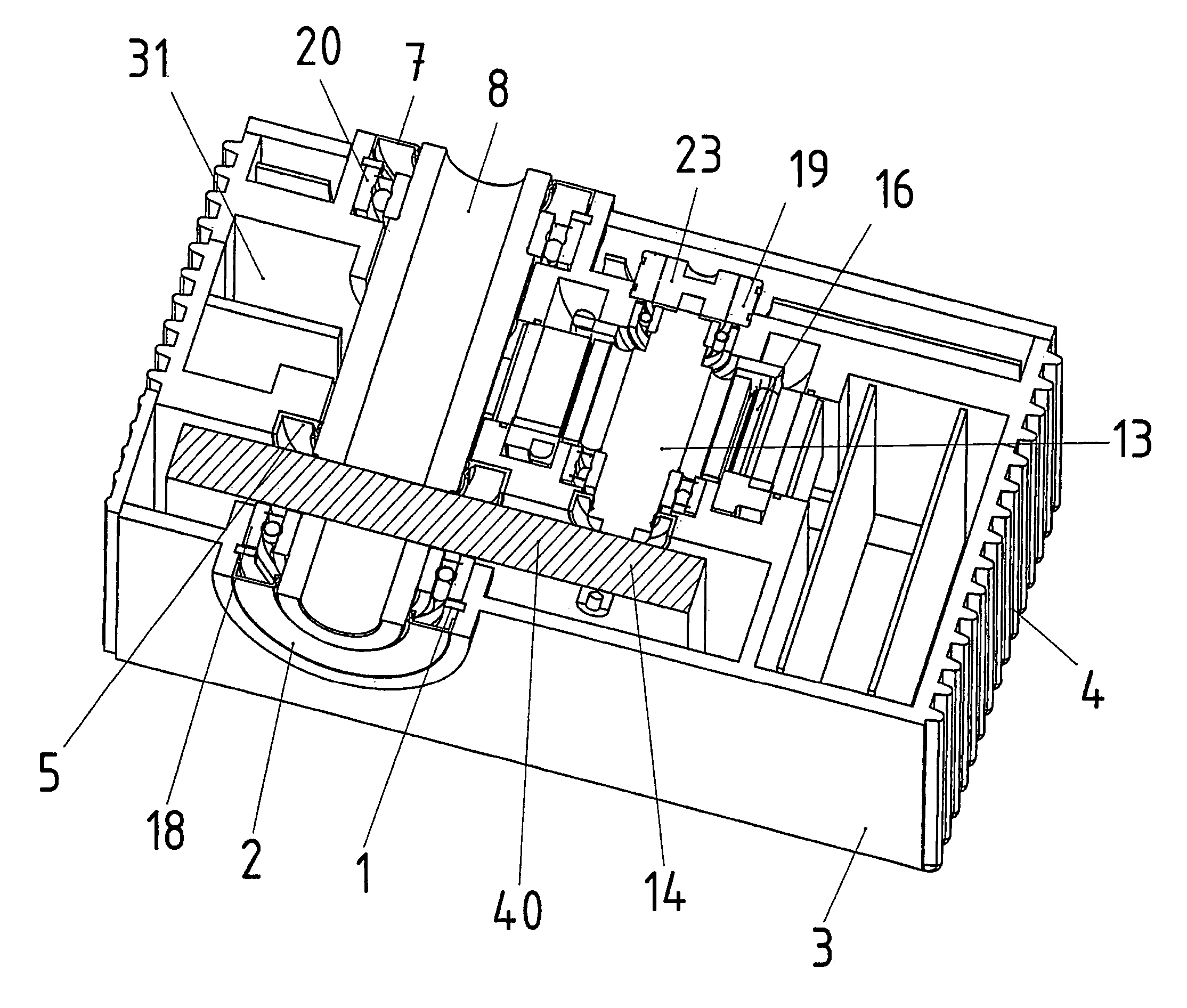
Figure 1 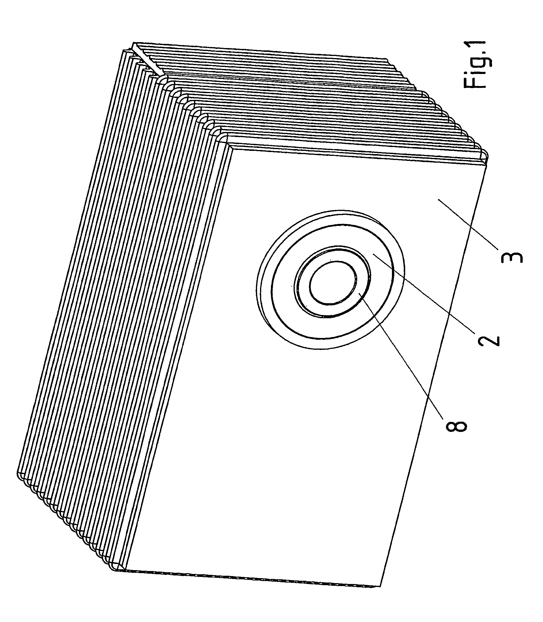
Figure 2 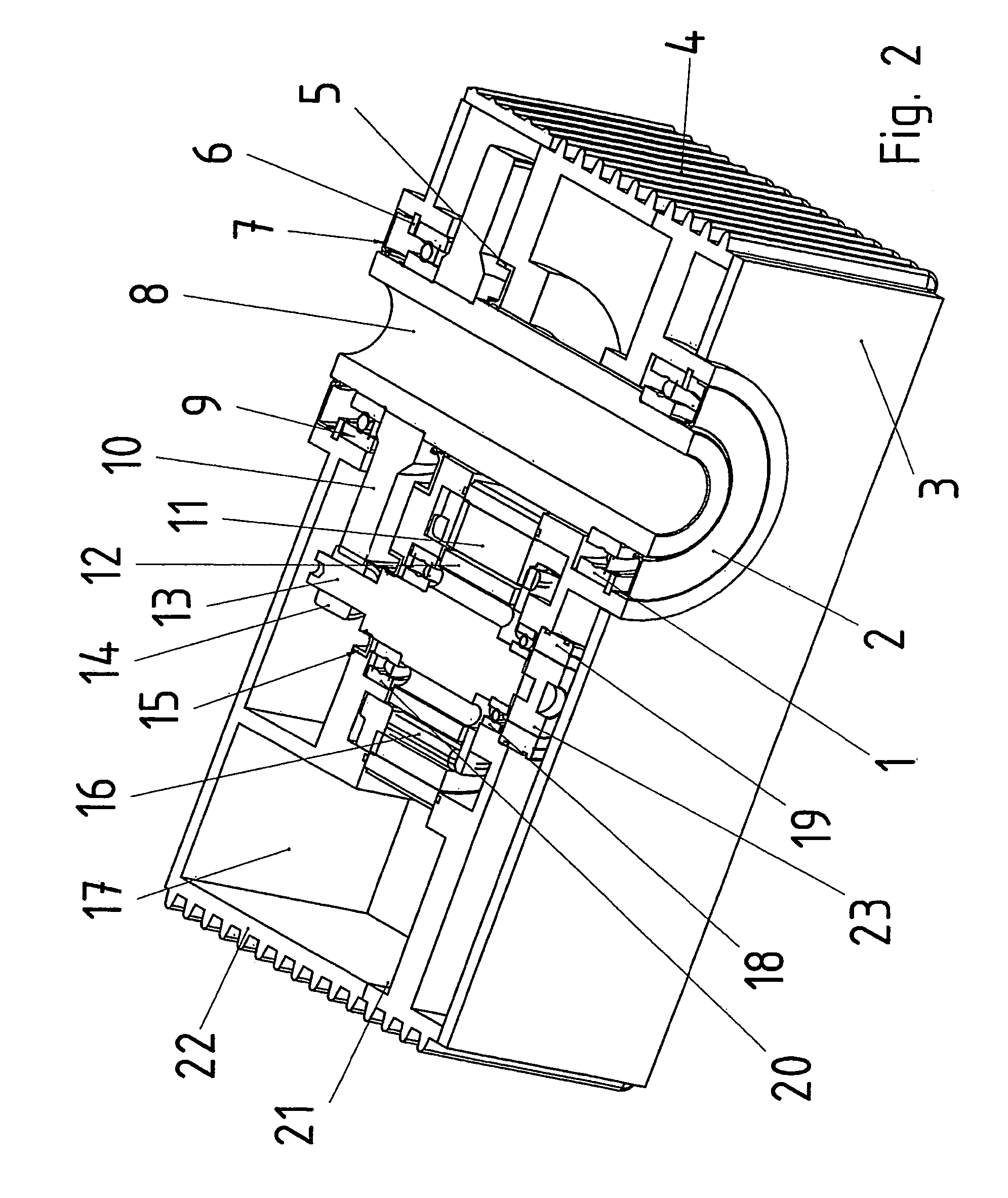
Figure 3
Abstract
Description
FIELD OF THE INVENTION
[0001] The present invention relates to a compact drive.BACKGROUND INFORMATION
[0002] German Published Patent Application No. 197 14 784 describes a compact drive, which includes an electric motor, at whose one end face a transmission is situated, and at whose other end face a frequency converter is situated. The electronics region and the motor region must be sealed with respect to the transmission. In this context, it may be disadvantageous that the axial length is long and that a power take-off can only be provided at one end face of the compact drive.SUMMARY
[0003] An example embodiment of the present invention may provide a compact drive that may eliminate the above-mentioned disadvantages. For example, axial length may be reduced and as many power take-off variants as possible may be implementable, i.e., one-sided and two-sided power take-off.
[0004] A compact drive according to an example embodiment of the present invention may include at least an electric moto...
Examples
Embodiment Construction
[0077]An oblique view of a compact drive according to an example embodiment of the present invention is illustrated in FIG. 4, whereby transmission 40 is illustrated schematically.
[0078]A perspective view of a compact drive according to an example embodiment of the present invention is illustrated in FIG. 1.
[0079]A cross-sectional view of the compact drive illustrated in FIG. 1 is illustrated in FIG. 2.
[0080]Illustrated in FIG. 3 is a cross-sectional view of a compact drive according to an example embodiment of the present invention, where, in contrast to FIG. 2, the frequency converter and the motor are arranged on different sides of the output shaft.
[0081]Illustrated in FIG. 5 is an exemplary embodiment of the present invention, in which a three-stage transmission is implemented.
[0082]FIG. 6 is a view different from that in FIG. 5.
[0083]FIG. 7 is an external view of the exemplary embodiment illustrated in FIG. 5.
[0084]In each instance, transmission 40 symbolically indicated in FIG...