
Brushless motor
a brushless motor and inner rotor technology, applied in the direction of windings, dynamo-electric components, magnetic circuit shapes/forms/construction, etc., can solve the problems of inability to secure a large winding space for the coil, inability to create useless space, and large wall thickness of the stator core, so as to achieve a firm wounding, improve the occupancy of the coil, and loosen the tension
Patent Information
- Authority / Receiving Office
- US · United States
- Patent Type
- Patents(United States)
- Current Assignee / Owner
- Publication Date
- 2010-02-16
- Estimated Expiration
- Not applicable · inactive patent
Smart Images
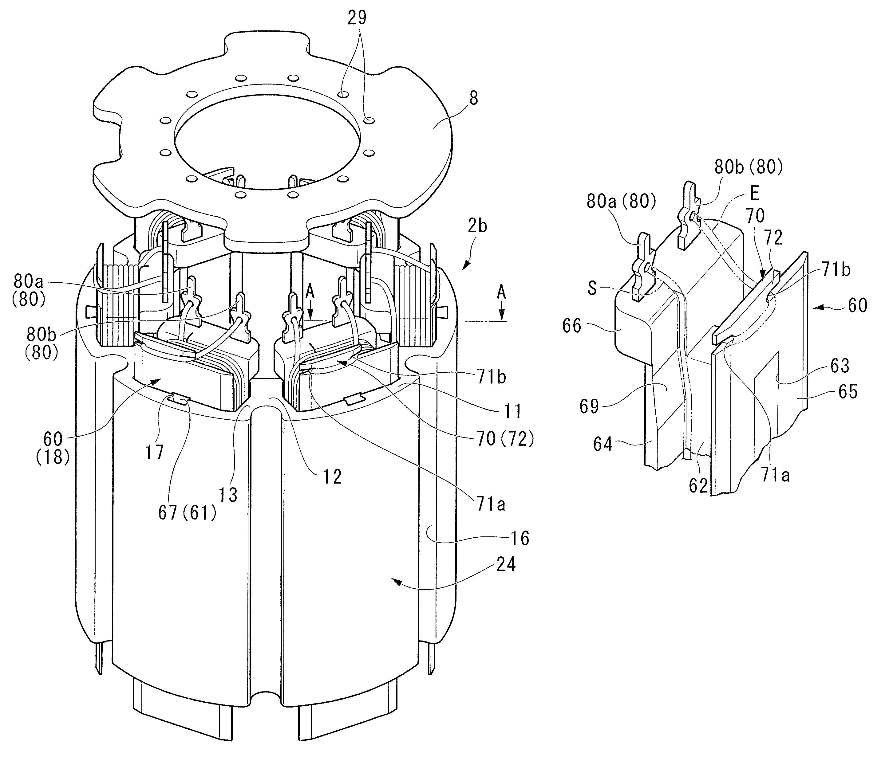
Figure 1 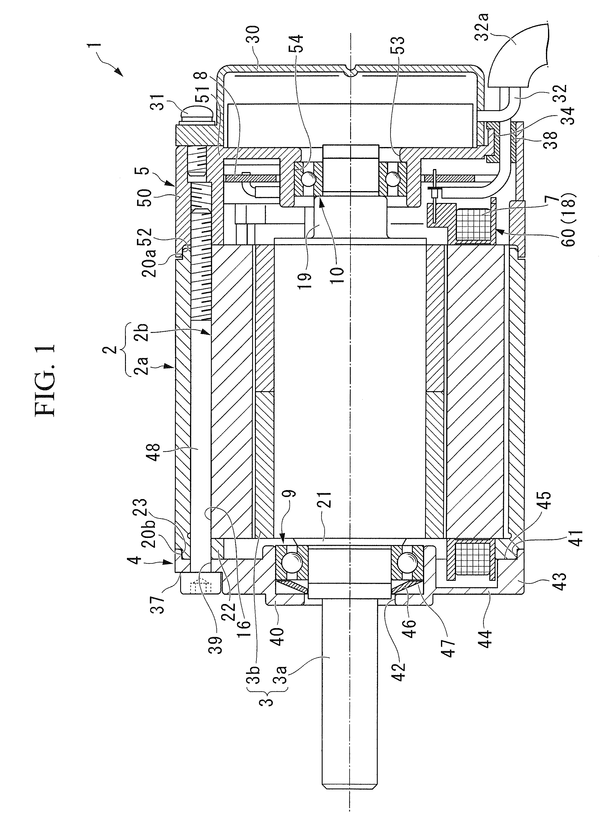
Figure 2 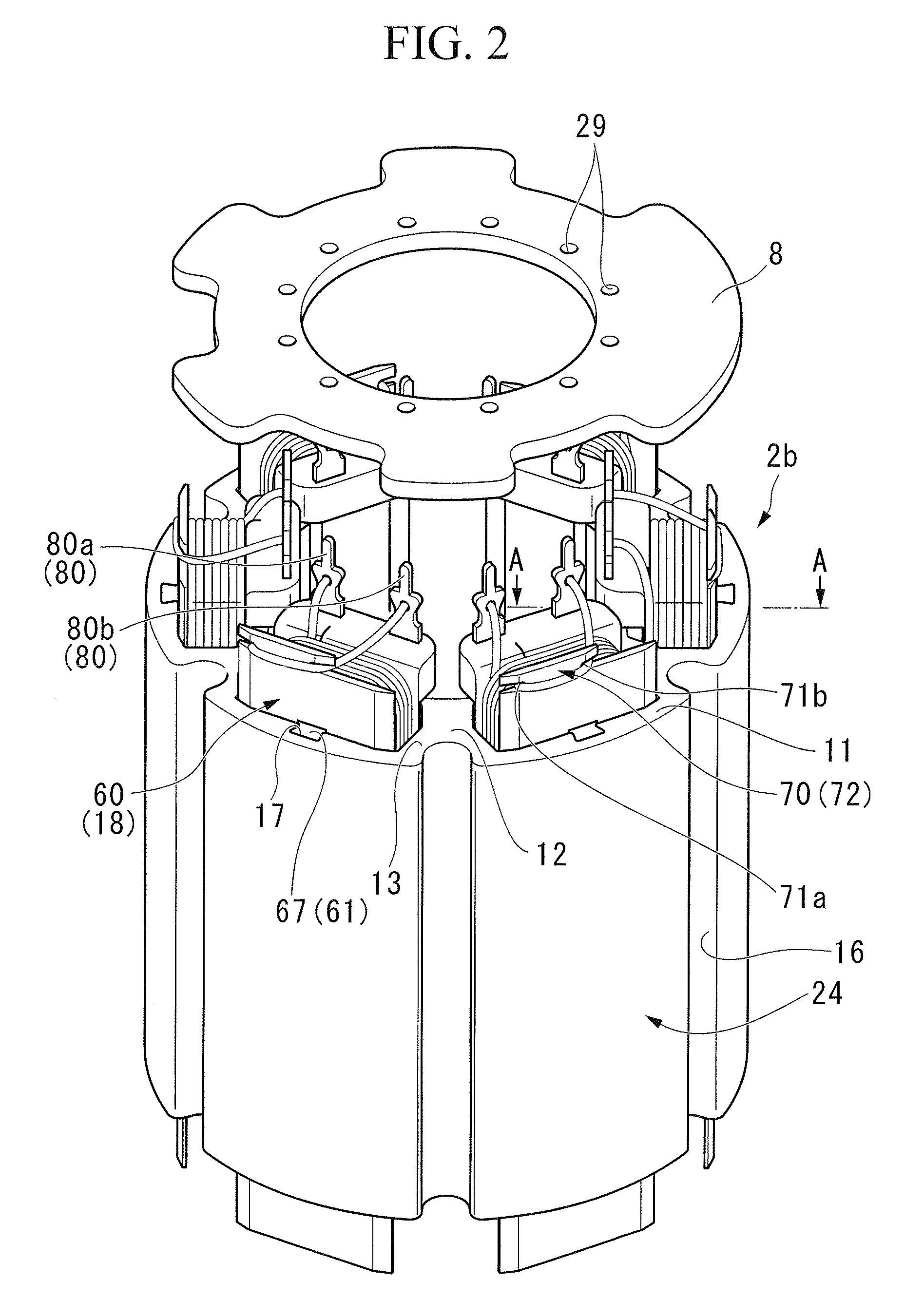
Figure 3
Abstract
Description
BACKGROUND OF THE INVENTION
[0001] Priority is claimed on Japanese Patent Application No. 2007-287863, filed on Nov. 5, 2007, the contents of which are incorporated herein by reference.
[0002] 1. Field of the Invention
[0003] The present invention relates to an inner rotor type brushless motor which has, for example, a rotor and a stator.
[0004] 2. Description of the Related Art
[0005] Generally, an inner rotor type brushless motor has a stator core fitted into and fixed to a stator case, and a rotor rotatably provided with respect to the stator core, and includes permanent magnets at an outer peripheral portion thereof. This stator core includes a plurality of teeth which protrude radially inward. A coil bobbin around which a coil is wound is mounted on each of the teeth. As electric current flows into the coil, an attractive or repulsive force is generated between the rotor and the stator to rotate the rotor.
[0006] Among this type of coil bobbin, for example, there is one which is constitute...
Examples
Embodiment Construction
[0017]Next, an embodiment of the invention will be described with reference to the drawings.
[0018]In the following description, the left side of FIG. 1 is defined as the front side (other end side), and the right side of FIG. 1 is defined as the rear side (one end side).
[0019]As shown in FIGS. 1 to 3, a brushless motor 1 of this embodiment is an inner rotor type brushless motor 1, and includes a substantially cylindrical stator 2, and a rotor 3 rotatably provided inside the stator 2.
[0020]The stator 2 includes a substantially cylindrical stator case 2a, and a stator core 2b fitted into and fixed to the stator case 2a.
[0021]The stator core 2b is formed by laminating a magnetic sheet material axially or pressing magnetic metal powder, and includes a tubular yoke portion 11. At an inner peripheral surface of the yoke portion 11, six commutating-pole teeth 12 which protrude radially inward are integrally formed at equal intervals in the peripheral direction of the yoke portion 11.
[0022...