
Inter-cervical facet implant and method for preserving the tissues surrounding the facet joint
a facet implant and intracervical technology, applied in the field of intracervical facet implants, can solve the problems of reducing the foraminal area, radicular pain, neck pain and muscle weakness,
Patent Information
- Authority / Receiving Office
- US · United States
- Patent Type
- Patents(United States)
- Current Assignee / Owner
- Publication Date
- 2012-01-24
- Estimated Expiration
- Not applicable · inactive patent
Smart Images
Figure 1 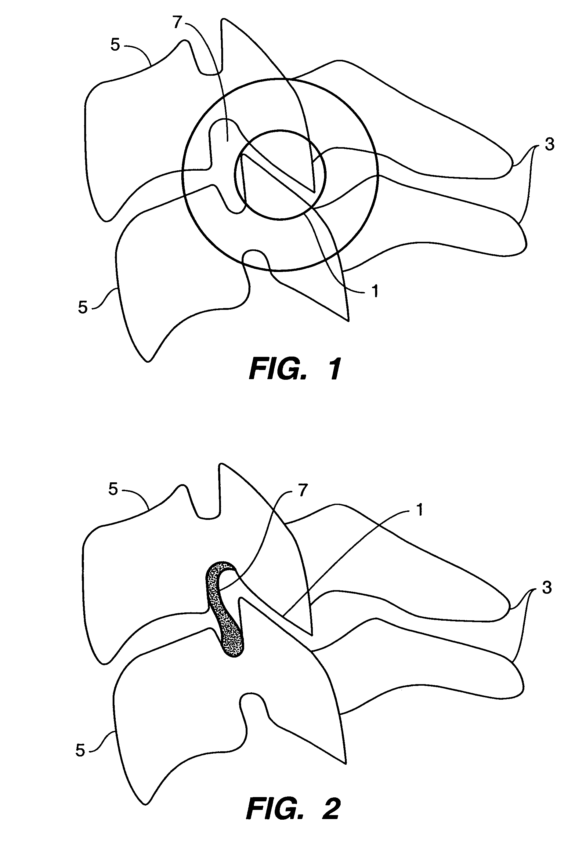
Figure 2 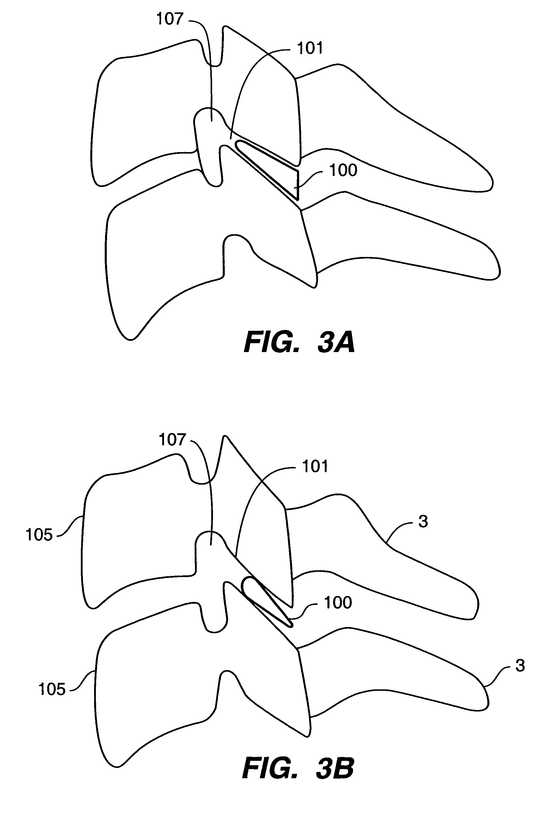
Figure 3
Abstract
Description
CLAIM OF PRIORITY
[0001] This application claims priority to U.S. Provisional Application, entitled, INTER-CERVICAL FACET IMPLANT AND METHOD filed Dec. 13, 2004, Ser. No. 60 / 635,453, which is incorporated herein by reference.CROSS-REFERENCE TO RELATED APPLICATIONS
[0002] This application is related to U.S. patent application Ser. No. 11 / 053,399, entitled INTER-CERVICAL FACET IMPLANT AND METHOD, filed Feb. 8, 2005; U.S. patent application Ser. No. 11 / 053,624, entitled INTER-CERVICAL FACET IMPLANT AND METHOD, filed Feb. 8, 2005; U.S. patent application Ser. No. 11 / 053,735, entitled INTER-CERVICAL FACET IMPLANT AND METHOD, filed Feb. 8, 2005; U.S. patent application Ser. No. 11 / 053,346, entitled INTER-CERVICAL FACET IMPLANT AND METHOD, filed Feb. 8, 2005; and U.S. patent application Ser. No. 11 / 093,557, entitled INTER-CERVICAL FACET IMPLANT WITH LOCKING SCREW AND METHOD, filed Mar. 30, 2005 each of which is incorporated herein in full, by reference.TECHNICAL FIELD
[0003] This invention relat...
Examples
embodiment 500
[0071]FIG. 8 shows a further embodiment 500 of the implant of the invention, wherein the joint insert or inter-facet spacer 510 has a keel 550 on an underside of the joint insert or inter-facet spacer 510. The keel 550 can be made of the same material or materials set forth above. The surfaces of the keel 550 can be roughened in order to promote bone ingrowth to stabilize and fix the implant 500. In other embodiments, the keel 550 can be coated with materials that promote bone growth such as, for example, bone morphogenic protein (“BMP”), or structural materials such as hyaluronic acid “HA,” or other substances which promote growth of bone relative to and into the keel 550.
[0072]The keel 550 can be embedded in the facet bone, to facilitate implant retention. The keel 550 can be placed into a channel in the facet bone. The channel can be pre-cut. Teeth (not shown), preferably positioned posteriorly, also may be formed on the keel 550 for facilitating retention of the implant 500 in t...
embodiment 900
[0076]FIG. 12 shows yet another embodiment 900 of an implant of the present invention. In this embodiment 900, the joint inserts or inter-facet spacers 910 of two implants 900 are positioned in a cervical facet joint 901. As described above, the joint inserts or inter-facet spacers 910 can be wedge-shaped as needed to restore anatomical curvature of the cervical spine and to distract, or the joint inserts or inter-facet spacers 910 can be of substantially uniform thickness. The implants 900 each comprise a joint insert or inter-facet spacer 910 with an outer surface 970 that interacts with the bone of the cervical facet joint 901. On the upper implant 900, the surface 970 that interacts with the bone is the upper surface 970 and on the lower implant 900, the surface 970 that interacts with the bone is the lower surface 970. Each surface 970 can comprise a bone ingrowth surface 980 to create a porous surface and thereby promote bone ingrowth and fixation. One such treatment can be wi...
embodiment 1000
[0077]FIG. 13 depicts yet another embodiment 1000 of the implant of the present invention. In this embodiment 1000, the joint inserts or inter-facet spacers 1010 of two implants 1000 are positioned in a cervical facet joint 1001. As described above, the joint inserts or inter-facet spacers 1010 can be wedge-shaped as needed to restore anatomical curvature of the cervical spine and to distract, or the joint inserts or inter-facet spacers 1010 can be of substantially uniform thickness. The implants 1000 each comprise a joint insert or inter-facet spacer 1010 with an outer surface 1070 that interacts with the bone of the cervical facet joint 1001. On the upper implant 1000, the surface 1070 that interacts with the bone is the upper surface and on the lower implant 1000, the surface 1070 that interacts with the bone is the lower surface. As set forth above, each outer surface 1070 can comprise a bone ingrowth surface 1080 to create a porous surface and thereby promote bone ingrowth and ...