
Solid-liquid separator using roller system
a technology of solid-liquid separator and roller system, which is applied in the direction of filtration separation, sedimentation settling tank, separation process, etc., can solve the problems of large load on the screen, leakage of solid-liquid mixture from gaps other than the filtration surface, damage, etc., to achieve high sealability, constant water content of okara, and heighten the effect of fitting or plane accuracy
Patent Information
- Authority / Receiving Office
- US · United States
- Patent Type
- Patents(United States)
- Current Assignee / Owner
- Publication Date
- 2013-08-13
- Estimated Expiration
- Not applicable · inactive patent
Smart Images
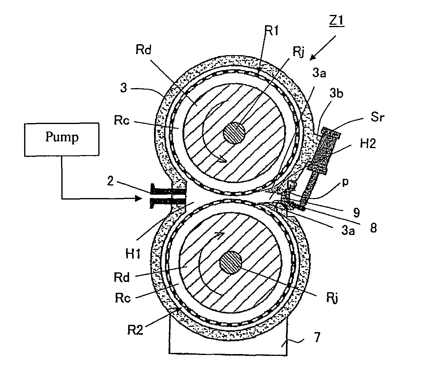
Figure 1 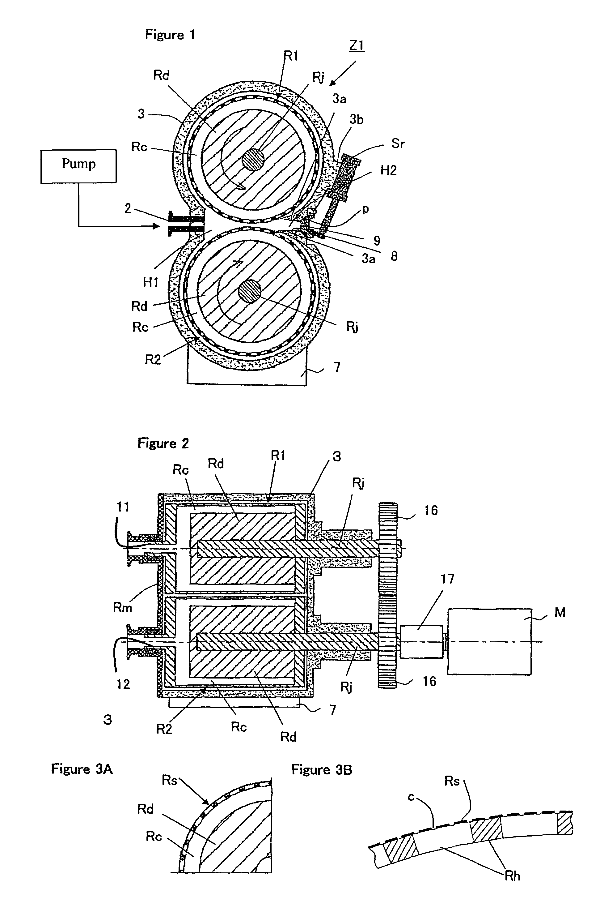
Figure 2 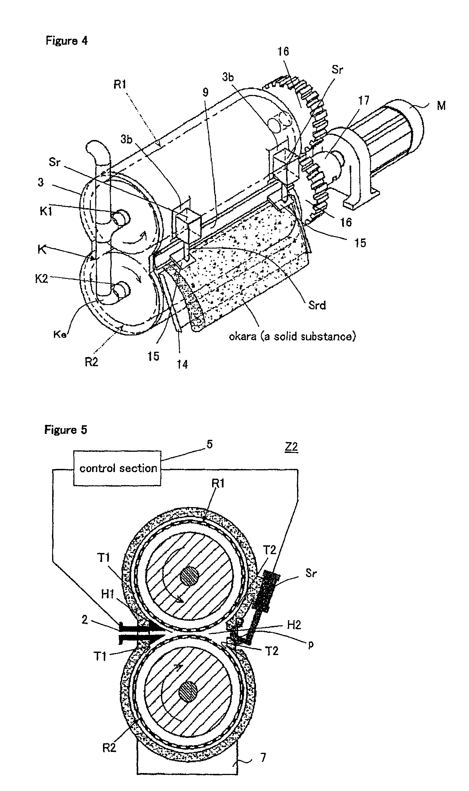
Figure 3
Abstract
Description
RELATED APPLICATIONS
[0001] The present application is based on, and claims priority from, Japanese Application No. JP2009-255859, filed Nov. 9, 2009, the disclosure of which is hereby incorporated by reference herein in its entiretyBACKGROUND OF THE INVENTION
[0002] 1. Field of the Invention
[0003] The present invention relates to a solid-liquid separator using a roller system, equipped with rollers each having a screen formed in the outer periphery thereof with plural pores, for separating a solid-liquid mixture into a solid component and a liquid component via the plural pores.
[0004] 2. Description of the Prior Art
[0005] There has heretofore been known a solid-liquid mixture separator for separating liquid through filtration from a solid-liquid mixture having a solid substance and a liquid substance mixed with each other, in which cited as the solid-liquid mixture is a solid-liquid mixture (so-called “boiled soybean-water slurry” that is hereinafter referred to also as “soybean soup” in ...
Examples
second embodiment
[0058]FIG. 6 is a cross section showing a solid-liquid separator Z3 having a roller system according to the present invention. In the present embodiment, paired scrapers 6 are attached as directed to the upper and lower rollers R1 and R2, respectively. That is to say, unlike the solid-liquid separator Z2 having the roller system, the passageway T1 and T2 are not provided here. The paired scrapers 6 are disposed to guide, without any modification, the solid-liquid mixture that has been supplied and passed between the upper and lower rollers R1 and R2 in the direction of the discharge window 8. That is to say, a region H2 on the discharge side is defined by the upper and lower rollers R1 and R2, the upper and lower scrapers 6 and a pressure application lid 9 on the wall of a casing 3 that is disposed close to the scrapers. It is possible for the upper and lower scrapers 6 to be attached as being spread in proportion as the scrapers are directed toward the discharge window 8. In this c...
first embodiment
[0059]In addition, a region H1 on the supply side is set to be larger than the region H2 on the discharge side. In comparison with the first embodiment, therefore, the solid-liquid mixture to be supplied from the region H1 on the supply side can readily pass through the region H2 on the discharge side to allow the solid component in a half-extracted state to readily pass in synchronization with the rotation of the rollers. For this reason, the extraction time can be shortened to enhance the apparatus performance, make the phenomenon of the solid substance rubbing the surface of the screens on the rollers (the so-called “grater” phenomenon) hard to occur and enable the liquid component (soymilk) containing a small amount of minute solid substances (residues in the soymilk, for example) to be obtained. In addition, when the cross-sectional area of the solid substance to be discharged becomes large, the solid substance always filling the region H2 on the discharge side causes the entir...