
Exhaust treatment device for a diesel engine
a treatment device and diesel engine technology, applied in auxillary pretreatment, electrical control, separation processes, etc., can solve the problems long cancel period, and dpf may be thermally damaged, so as to prevent the cancel period from becoming, prevent the effect of thermal damage to dpf 1 when regenerating dp
Patent Information
- Authority / Receiving Office
- US · United States
- Patent Type
- Patents(United States)
- Current Assignee / Owner
- Publication Date
- 2014-06-24
Smart Images
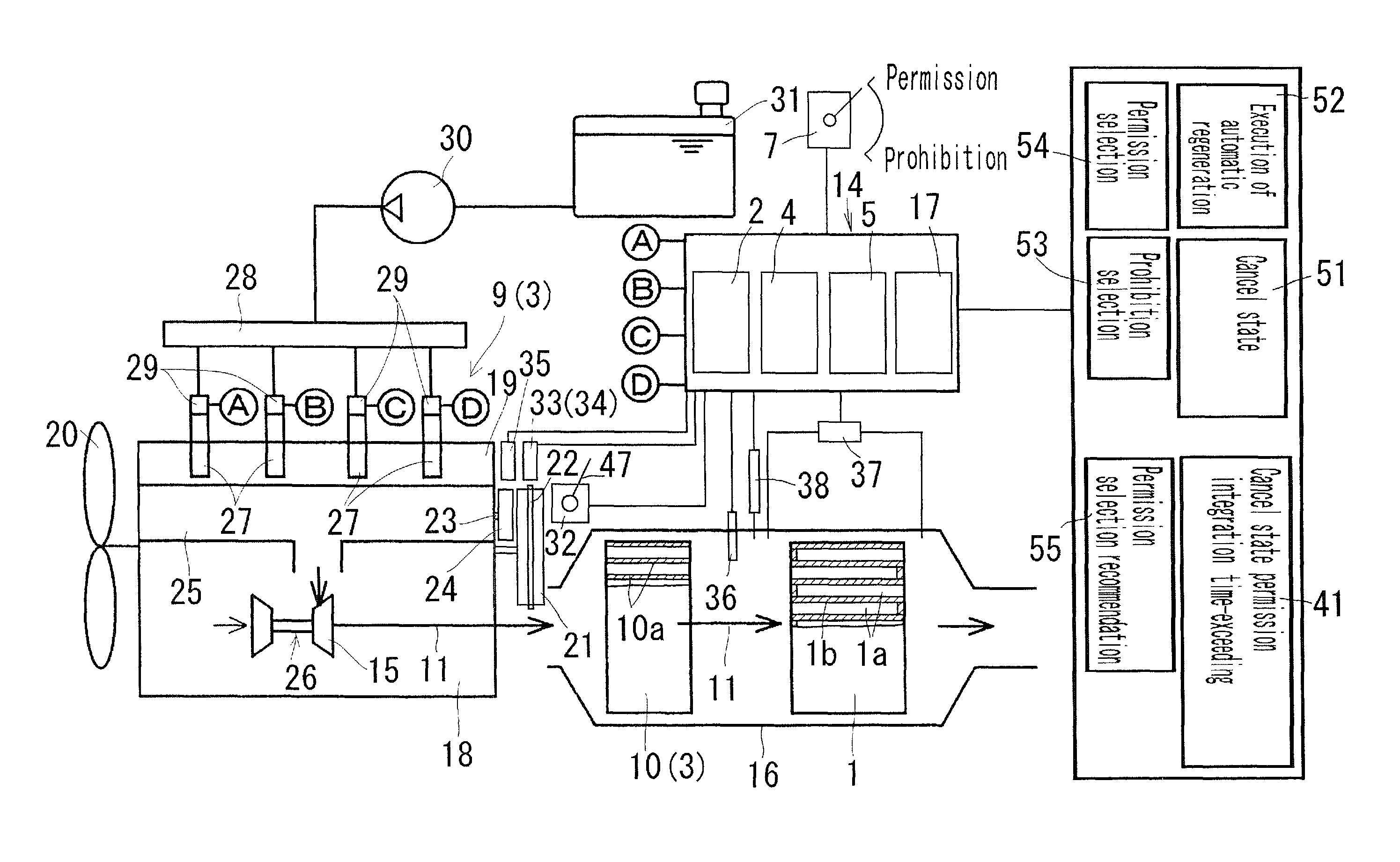
Figure 1 
Figure 2 
Figure 3
Abstract
Description
CROSS-REFERENCE TO RELATED APPLICATION
[0001] This application is a Section 371 of International Application No. PCT / JP2011 / 056178, filed Mar. 16, 2011, which was published in the Japanese language on Sep. 29, 2011, under International Publication No. WO 2011 / 118464 A1, and the disclosure of which is incorporated herein by reference.TECHNICAL FIELD
[0002] The present invention relates to an exhaust treatment device for a diesel engine and, more particularly, to an exhaust treatment device for a diesel engine which is capable of preventing thermal damage to a DPF when regenerating the DPF.
[0003] From among terms in the present invention, a DPF is an abbreviation of a Diesel Particulate Filter, a PM is an abbreviation of Particulate Material included in an exhaust gas, and a DOC is an abbreviation of a diesel oxidation catalyst.BACKGROUND ART
[0004] Conventionally, a DPF regeneration control device starts the execution of automatic DPF regeneration processing based on the fact that the accum...
Examples
Embodiment Construction
[0057]FIGS. 1 to 4 are diagrams illustrating an exhaust treatment device for a diesel engine relating to embodiments of the present invention. In the present embodiment, a common rail type multi-cylinder diesel engine equipped with the exhaust treatment device is described below.
[0058]An outline of the diesel engine shown in FIG. 1 is described below.
[0059]A cylinder head 19 is assembled over the cylinder block 18, an engine cooling fan 20 is disposed at the fore part of the cylinder block 18, a fly wheel 21 is disposed at the rear part of the cylinder block 18, and a rotor plate 22 is mounted on the fly wheel 21. Furthermore, a sensor plate 24 mounted on a valve-driven cam shaft 23 is disposed at the rear part of the cylinder block 18. An exhaust manifold 25 is disposed on one side of the cylinder head 19, and a supercharger 26 communicates with the exhaust manifold 25. A DPF accommodating casing 16 in which a DPF 1 is accommodated is disposed in the lower stream of the turbine 15 ...