
Directional notch filter for simultaneous transmit and receive of wideband signals
a wideband signal and notch filter technology, applied in the field of simultaneous transmit and receive of wideband signals, can solve the problems of difficult to achieve the minimizing of the leakage of transmit signals into the receiver caused by antenna reflection in practice, and difficult to achieve reflection in practice. , to achieve the effect of selective suppression of transmitter leakage, selective cancellation of back-reflection, and selective suppression of digital signal processing methods
Patent Information
- Authority / Receiving Office
- US · United States
- Patent Type
- Patents(United States)
- Current Assignee / Owner
- Publication Date
- 2015-01-27
Smart Images
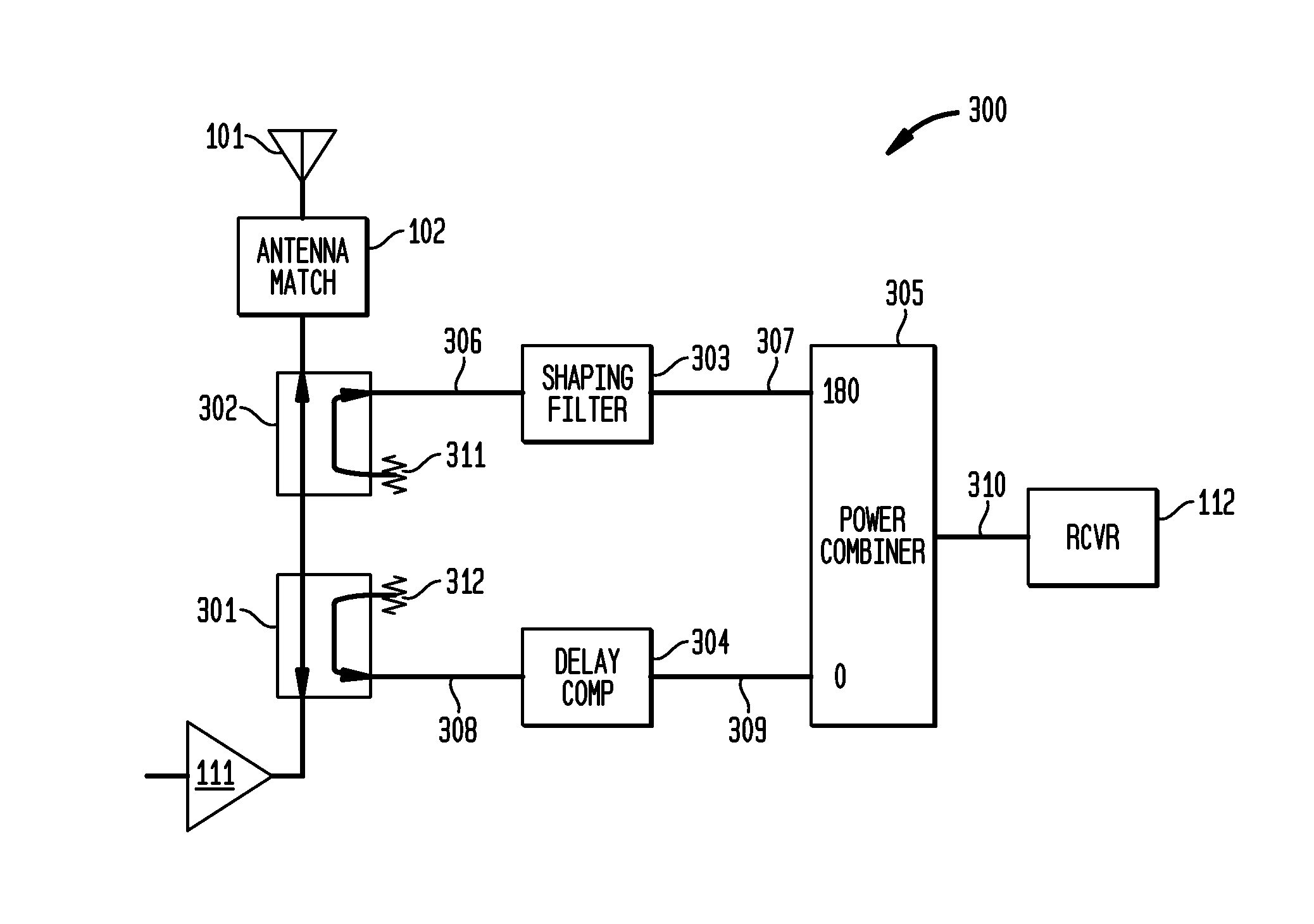
Figure 1 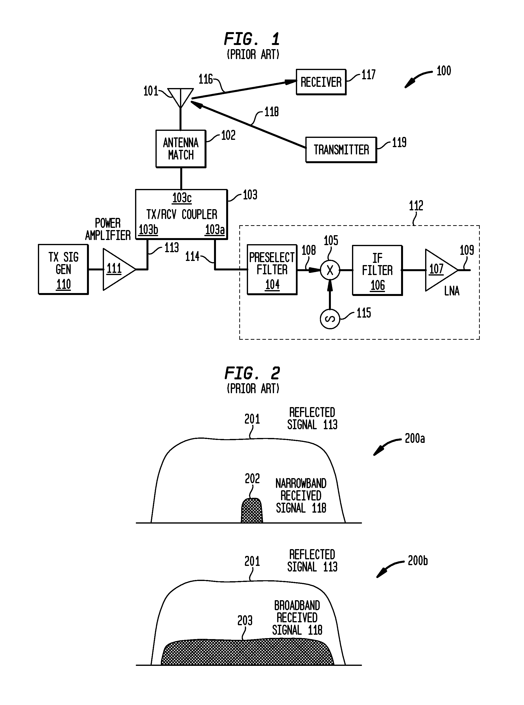
Figure 2 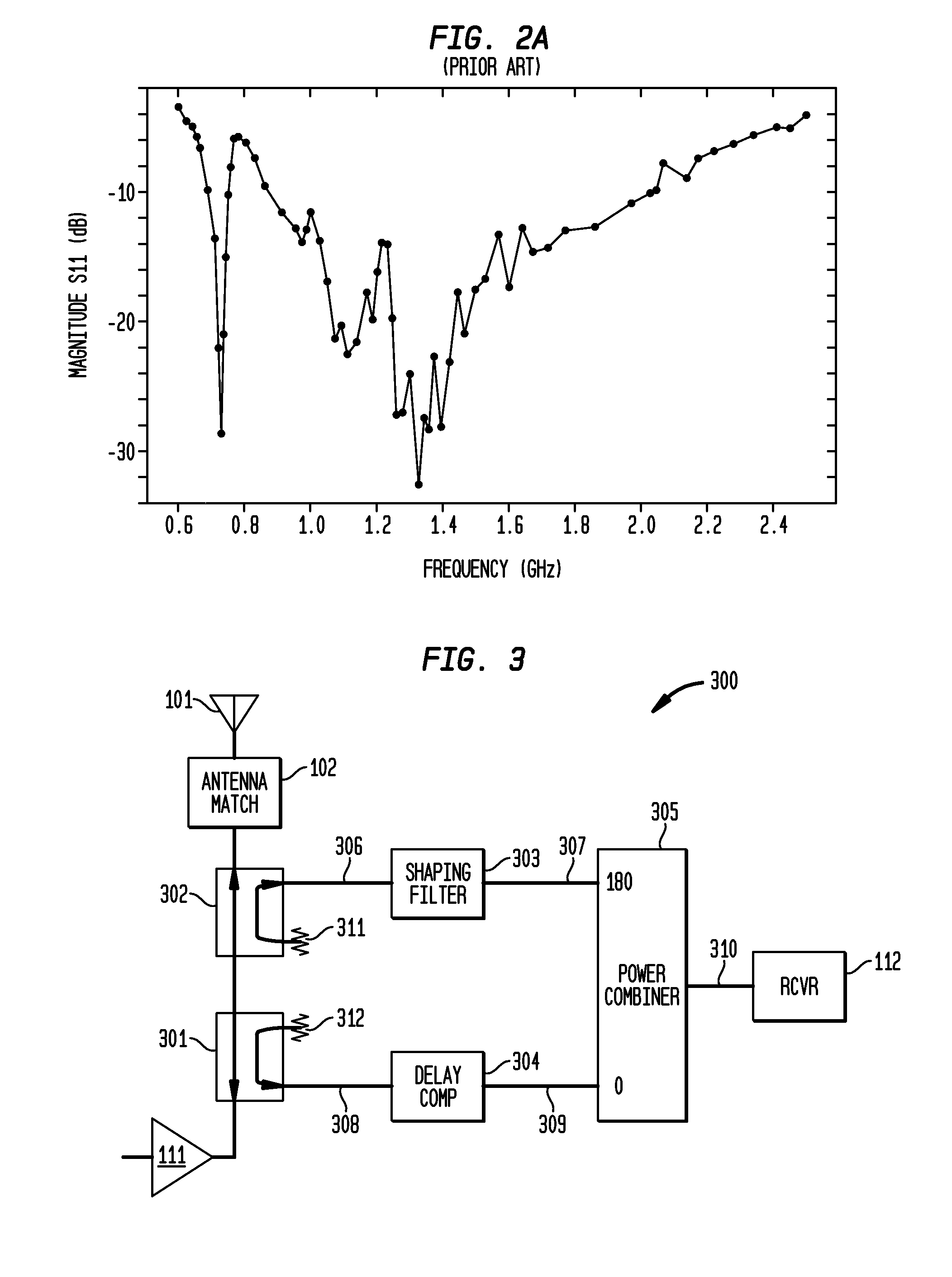
Figure 3
Abstract
Description
CROSS REFERENCE TO RELATED APPLICATIONS
[0001] The present invention claims the benefit of U.S. provisional patent application 61 / 482,746 filed May 5, 2011, the entire contents and disclosure of which are incorporated herein by reference as if fully set forth hereinFIELD OF THE INVENTION
[0002] This invention relates generally to wideband signals, wireless transmission, IED migration and, more specifically, to simultaneous transmit and receive of wideband signals.BACKGROUND OF THE INVENTION
[0003] There are several well known methods for implementing the transmit / receive coupler in a transceiver which both transmits and receives. For example, a Single Pole Double Throw (SPDT) switch is employed in a wide range of applications where talk and listen do not occur simultaneously, as with most transceivers using Time Division Multiplexing (TDM). Simultaneous transmit and receive (STAR) has been accomplished using a frequency diplexer, circulator or hybrid coupler as illustrated in FIG. 1. This...
Examples
Embodiment Construction
[0028]An inventive directional notch filter is presented.
[0029]FIG. 3 is a block diagram of the inventive directional notch filter 300 which is suitable for applications with wideband overlapping signals. The antenna coupler 103 of FIG. 1 is implemented in the inventive device using two directional couplers 301 and 302 with a frequency selective combiner. Directional coupler 301 produces signal 308 which is a portion (about 10% or −10 dB) of the signal received by antenna 101. Signal 308 is sent to the receiver 112 via power combiner 305. Signal 308 also includes reflection of signal 113 from power amplifier 111 by antenna 101 and antenna match 102. Directional coupler 302 samples a small portion (about 10% or −10 dB) of transmit signal 113 to produce signal 306. Shaping filter 303 accepts signal 306 and produces compensation signal 307 which is a replicate of the antenna reflection transfer function. Power combiner 305 subtracts compensation signal 307 from desired signal 306 to ca...