
Fixed oxide fuel cell
a fuel cell and fixed oxide technology, applied in the field of fixed oxide fuel cells, can solve the problems of fuel gas and oxidant gas undesired flow out of manifolds, difficult for glass-made seal portions to follow the relatively great variation,
Patent Information
- Authority / Receiving Office
- US · United States
- Patent Type
- Patents(United States)
- Current Assignee / Owner
- Publication Date
- 2015-06-09
- Estimated Expiration
- Not applicable · inactive patent
Smart Images
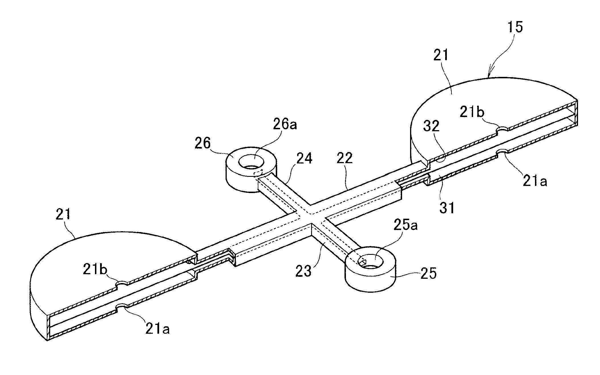
Figure 1 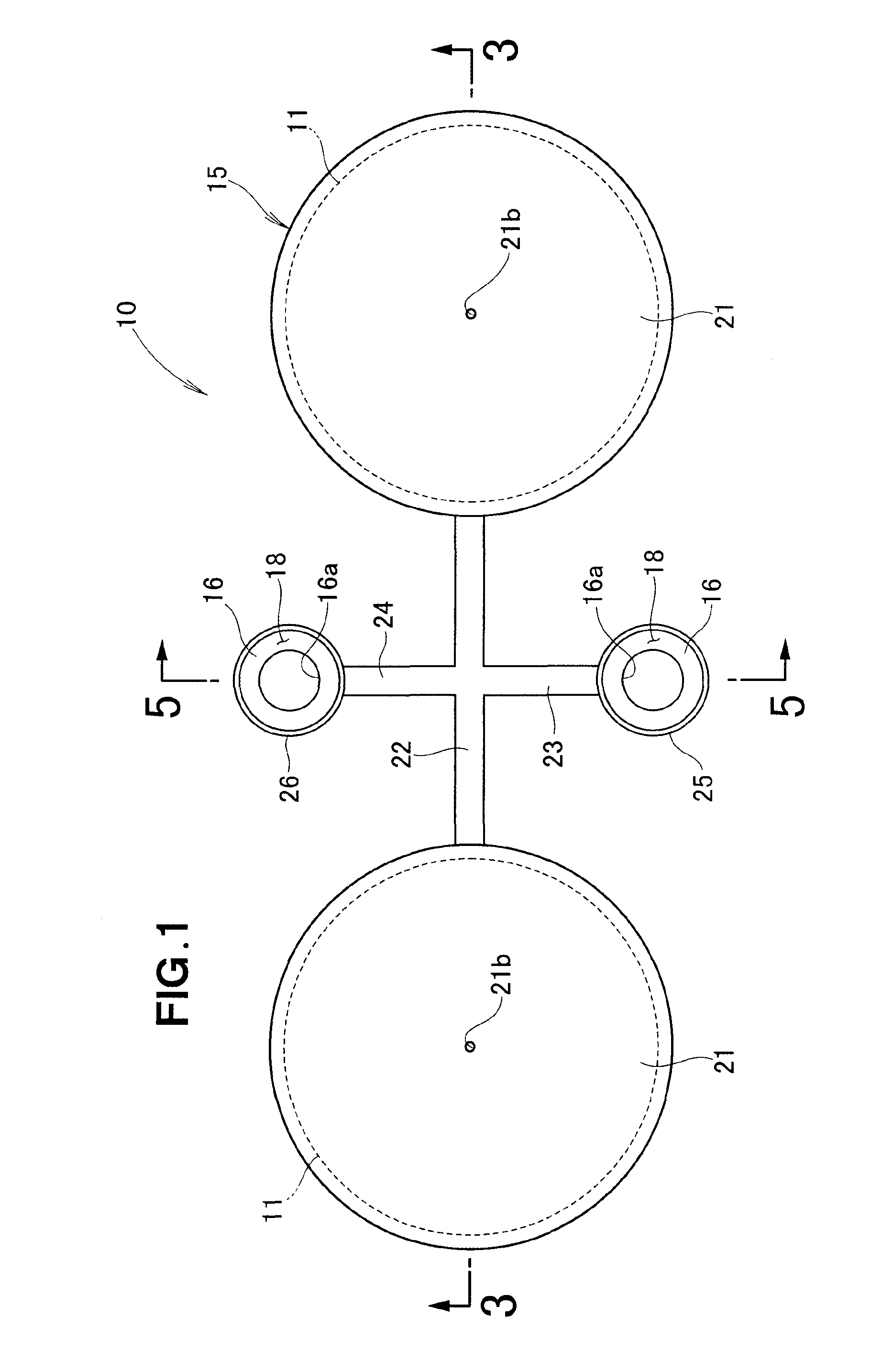
Figure 2 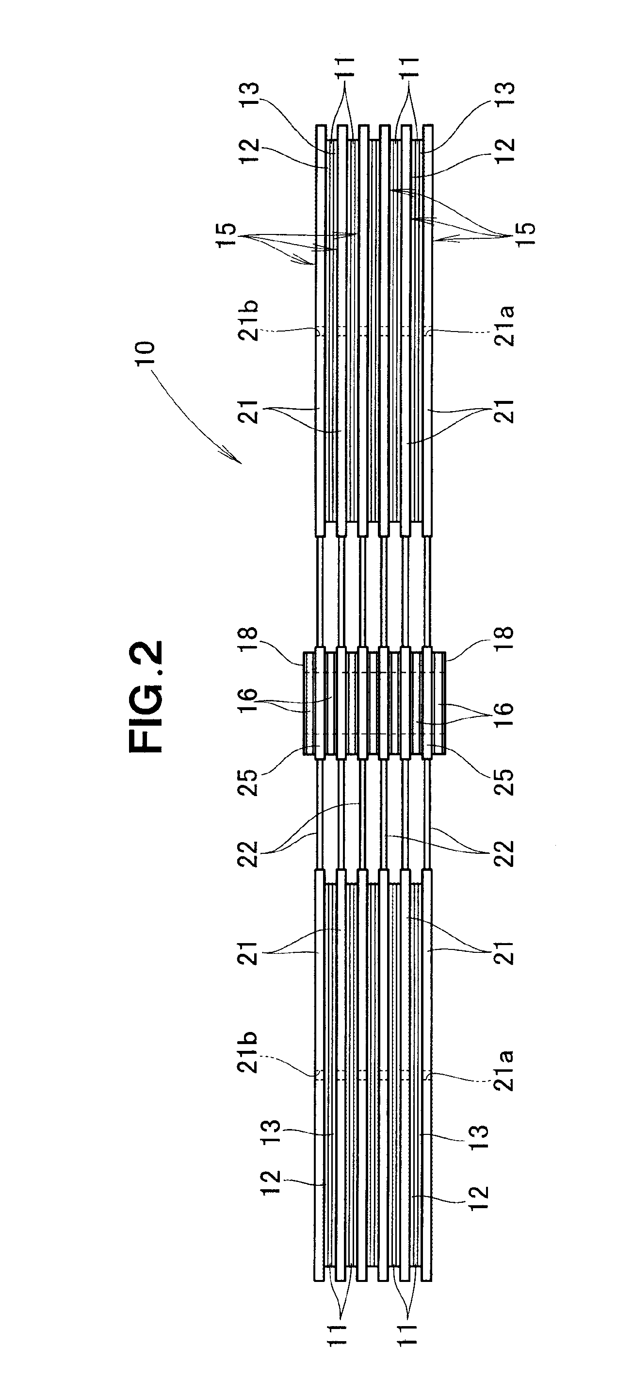
Figure 3
Abstract
Description
FIELD OF THE INVENTION
[0001] The present invention relates to fixed oxide fuel cells which include manifolds formed by separators sandwiching therebetween a membrane electrode assembly, and in which fuel gas and oxidant gas are supplied from the manifolds to the membrane electrode assembly.BACKGROUND OF THE INVENTION
[0002] Fixed oxide fuel cells are known which are constructed to provide desired outputs by means of a stack of a multiplicity of fuel cells. In each of the fuel cells, separators are provided on the opposite surfaces of a membrane electrode assembly (also referred to as “MEA”), i.e. sandwich the membrane electrode assembly, via current collectors. With the current collectors interposed between the separators and the MEA, it is possible to secure given contact areas between the MEA and the separators while allowing manufacturing errors of the MEA and separators.
[0003] In each of the separators are formed gas flow paths (or gas passages) for directing fuel gas and oxidant ga...
Examples
Embodiment Construction
[0026]Reference is now taken to FIG. 1 showing, in plan, an embodiment of a fixed oxide fuel cell, FIG. 2 is a side view of the fixed oxide fuel cell shown in FIG. 1, and FIG. 3 is a sectional view taken along the 3-3 line of FIG. 1. As shown in FIGS. 1 and 2, the fixed oxide fuel cell 10 comprises a stack of: a plurality of membrane electrode assemblies (MEAs) 11; a plurality of pairs of current collectors 12 and 13, each of the pairs disposed over the opposite surfaces 11a and 11b (see FIG. 3) of one of the MEAs 11; a plurality of separators 15, every adjoining two of them disposed over one of the pairs of current collectors 12 and 13; a plurality of insulating communication sections 16 each disposed between the separators 15; and a plurality of silver plate layers 18 each provided on one of the insulating communication sections 16 to seal between the one insulating communication sections 16 and one of the separators 15 adjoining the one insulating communication sections 16.
[0027]...