
Processor, processing system, data sharing processing method, and integrated circuit for data sharing processing
a processing system and integrated circuit technology, applied in the field of multi-processor systems, can solve the problems of increasing the possibility of unneeded contention with the processor, wasteful consumption of storage space in the dedicated memory b>3/b>c, etc., and achieve the effect of convenient managemen
Patent Information
- Authority / Receiving Office
- US · United States
- Patent Type
- Patents(United States)
- Current Assignee / Owner
- Publication Date
- 2015-11-03
Smart Images
Figure 1 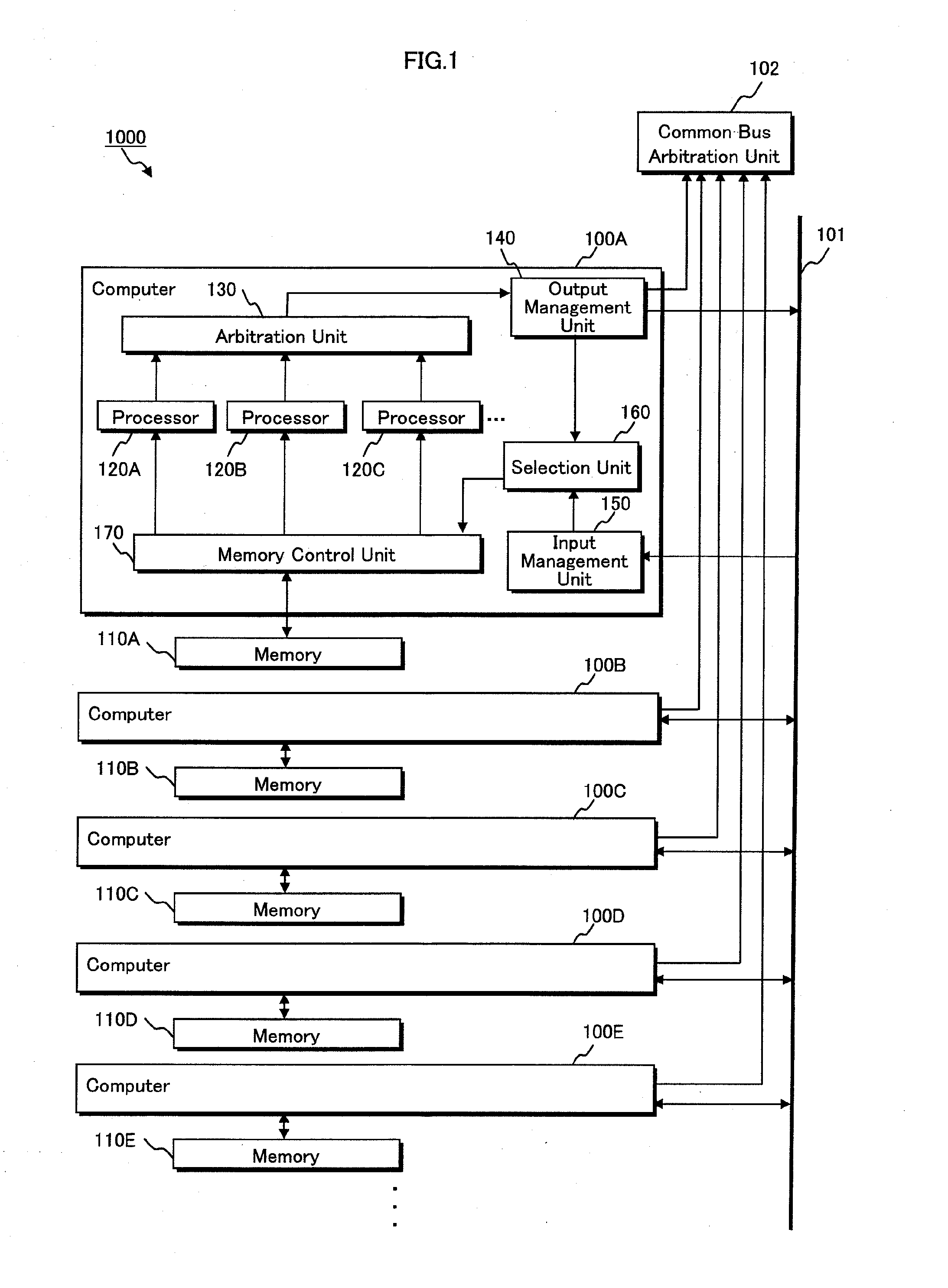
Figure 2 
Figure 3
Abstract
Description
BACKGROUND OF THE INVENTION
[0001] 1. Technical Field
[0002] The present invention relates to a multiprocessor system, and particularly to a technique for sharing data among processors.
[0003] 2. Background Art
[0004] As a method for sharing data among a plurality of processors in a multiprocessor system, the following method (so-called tightly-coupled multiprocessor system) is known. Data to be shared is stored in a single shared memory, and processors access this shared memory so as to share the data with one another.
[0005] This method has an advantage that the identity of shared data used by processors can be easily maintained. On the other hand, this method is problematic in that, as processors increase in number, they are more likely to contend with one another for accessing the shared memory, which results in lowering of the processing efficiency of the entire system.
[0006] This is particularly problematic in processes that require real-time performance, such as a process to receive dig...
Examples
embodiment 1
Configuration
[0107]Firstly, a description is given of a configuration of processing system 1000 pertaining to Embodiment 1.
[0108]FIG. 1 is a system configuration diagram showing the processing system 1000 pertaining to Embodiment 1.
[0109]As shown in FIG. 1, the processing system 1000 includes computers 100A-100E connected to each other via a common bus 101, memories 110A-110E connected in one-to-one-correspondence with the computers, and a common bus arbitration unit 102.
[0110]FIG. 1 shows five computers (100A-100E). Note that the number of the computers shown in FIG. 1 is merely an example. The computers may be provided in any number as long as the number is two or more. In addition, FIG. 1 shows an example where the computers are connected in one-to-one correspondence with the memories. However, each computer may be connected to two memories or more. These features also apply to the embodiments provided below.
[0111]Here, the common bus 101 is a bus by which the computers communica...
application example 1
[0202]First, a description is given of an example in which the processing system 1000 pertaining to Embodiment 1 is applied to the digital broadcasting receiver 1000A having a function of decoding MPEG (Moving Picture Experts Group).
[0203]FIG. 8 is a configuration diagram of a digital broadcasting receiver 1000A pertaining to Application Example 1.
[0204]As shown in FIG. 8, the digital broadcasting receiver 1000A includes the processing system 1000, an antenna, a tuner, a speaker, a monitor etc.
[0205]Note that, hereinafter, to simplify the description, the description is given on the following assumption. Each computer has only one processor 120A. The arbitration unit 102's arbitration of the right to use common bus 101 is not particularly referred (omitted in FIG. 8).
[0206]Here, the processor 120A in each computer (100A-100E) executes a program stored in an inherent area (storage area having stored therein other data than the shared data; this area is represented by a hatching porti...
application example 2
[0239]Subsequently, a description is given of an example where the method for sharing data with computers according to Embodiment 1 is applied to synchronization control of the computers of the above-mentioned digital broadcasting receiver 1000A.
[0240]Here, the synchronization control means controlling the entire system by causing a plurality of computers to perform simultaneous execution of predetermined processing. For example, in the digital broadcasting receiver 1000A, the computers simultaneously perform (i) switch processing of decode streams as a result of channel switching and (ii) error concealment, such as a picture skip due to an error regarding a stream, a buffer flush and the like.
[0241]First, a description is given of data stored in each memory.
[0242]FIG. 13A shows data placement in each memory in the digital broadcasting receiver 1000A pertaining to Application Example 2.
[0243]Note that a description is given that there are five computers (100A-100E) in the digital br...