
Image recording apparatus
a recording apparatus and image technology, applied in the direction of printing, other printing apparatus, etc., can solve the problems of difficult to ensure damage to the image recording apparatus, and difficulty in ensuring an adequate volume level and sound range, so as to improve the sound quality of the speaker uni
Patent Information
- Authority / Receiving Office
- US · United States
- Patent Type
- Patents(United States)
- Current Assignee / Owner
- Publication Date
- 2015-12-29
Smart Images
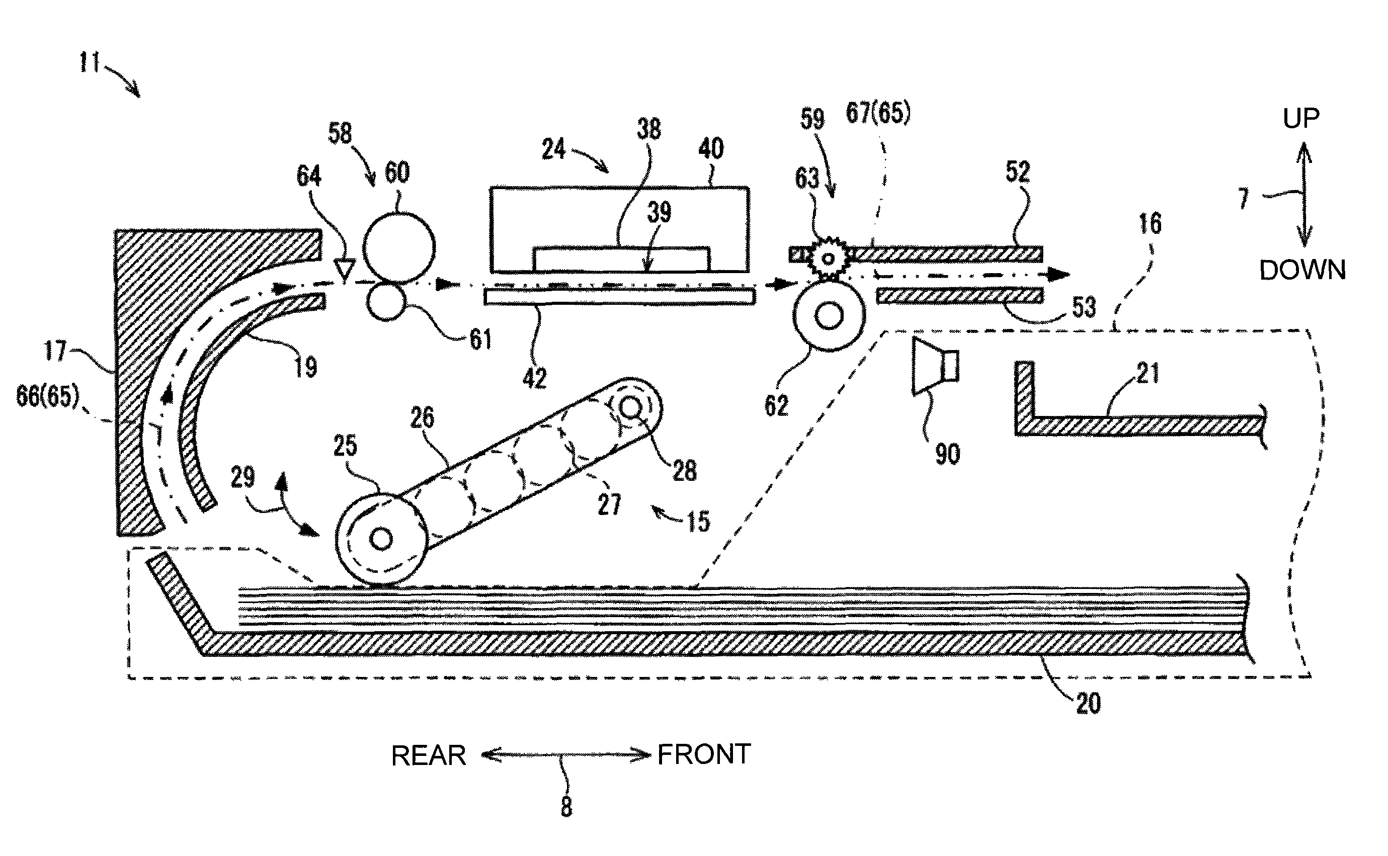
Figure 1 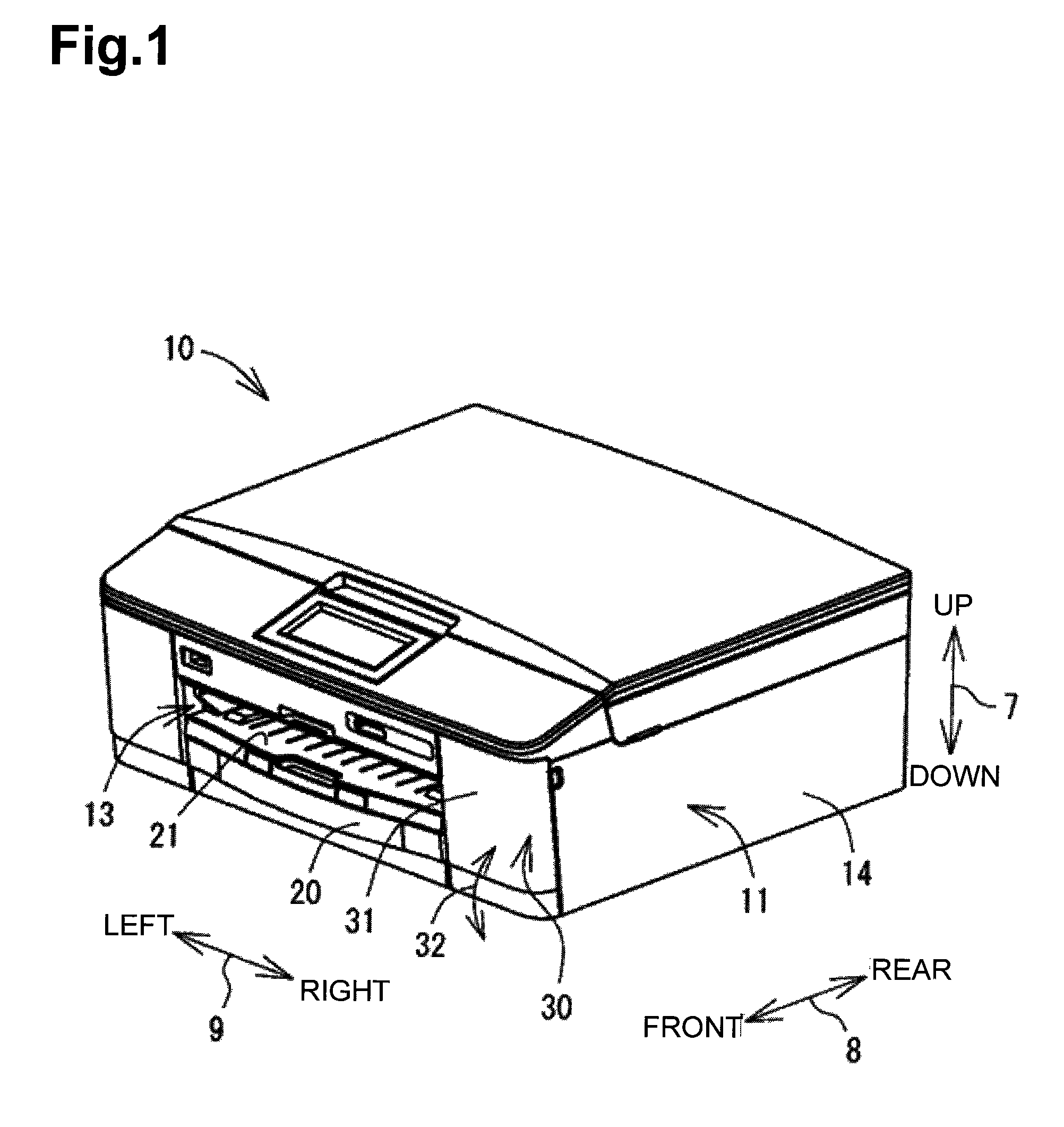
Figure 2 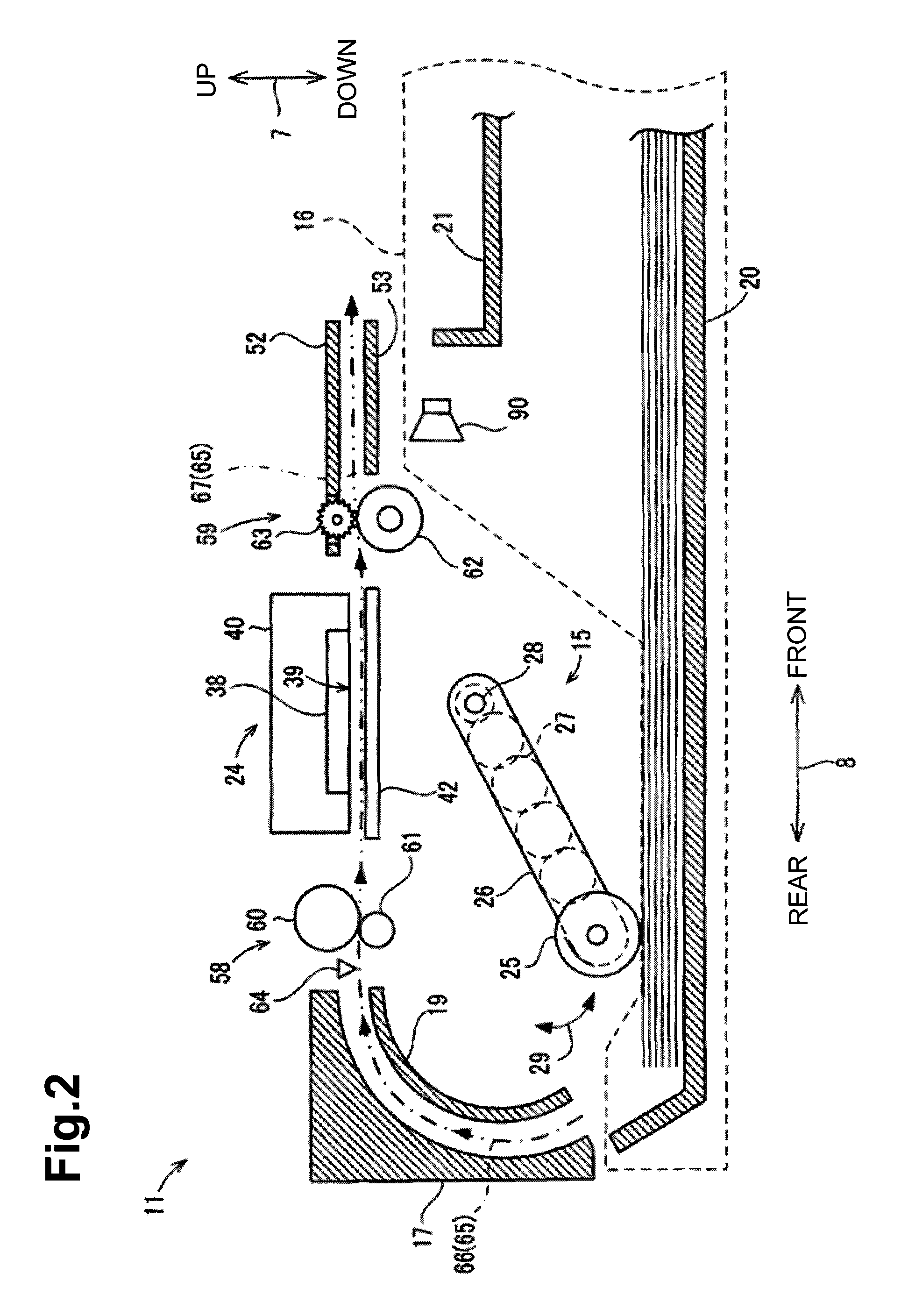
Figure 3
Abstract
Description
CROSS-REFERENCE TO RELATED APPLICATION
[0001] This application claims priority from Japanese Patent Application No. 2012-217557, filed on Sep. 28, 2012, which is incorporated herein by reference.BACKGROUND OF THE DISCLOSURE
[0002] 1. Field of the Disclosure
[0003] The disclosure relates generally to an image recording apparatus including a speaker.
[0004] 2. Description of Related Art
[0005] A known image recording apparatus includes a speaker that outputs a warning beep to inform a user of, for example, an occurrence of a trouble in the image recording apparatus or an occurrence of a paper-out condition. Generally, in the known image recording apparatus, the speaker is disposed inside a housing of the image recording apparatus and is configured to emit sound to the outside of the housing through small holes that go through a wall of the housing. Another image recording apparatus includes a speaker unit disposed outside its housing.
[0006] In recent years, still another image recording apparatu...
Examples
Embodiment Construction
[0029]An embodiment according to one or more aspects is described below with reference to the accompanying drawings. The embodiment described below is merely an example. Various changes, arrangements and modifications may be applied therein without departing from the spirit and scope of the invention. In the description below, an up-down direction 7 may be defined with reference to an orientation of a multifunction device 10 that may be disposed in an orientation in which it may be intended to be used (e.g., an orientation depicted in FIG. 1). A side of the multifunction device 10, in which an opening 13 may be defined, may be defined as the front of the multifunction device 10. A front-rear direction 8 may be defined with reference to the front of the multifunction device 10. A right-left direction 9 may be defined with respect to the multifunction device 10 as viewed from the front of the multifunction device 10.
[0030]As depicted in FIG. 1, the multifunction device 10 as an exampl...