Bracket

A technology of a support member and a support plate, applied in the field of brackets, can solve the problems of adjusting the viewing angle, users cannot adjust the support angle, etc.

Inactive Publication Date: 2011-04-20
HONG FU JIN PRECISION IND (SHENZHEN) CO LTD +1
View PDF0 Cites 10 Cited by
  • Summary
  • Abstract
  • Description
  • Claims
  • Application Information

AI Technical Summary

Problems solved by technology

[0003] However, the above-mentioned legs can only support the main body at a specific angle, and t

Method used


Image

  • Bracket
  • Bracket
  • Bracket

Examples


Embodiment Construction

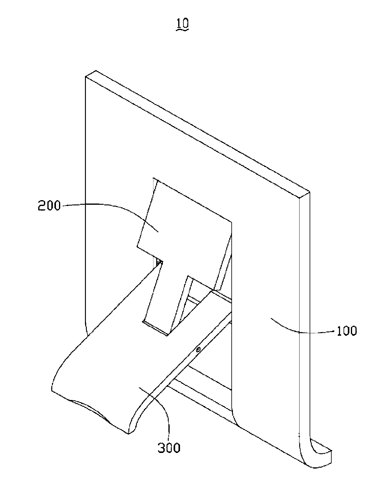
[0012] see figure 1 , which is a perspective view of a bracket 10 in a preferred embodiment. The bracket 10 includes a fixing component 100 , a pivoting component 200 and a supporting component 300 .

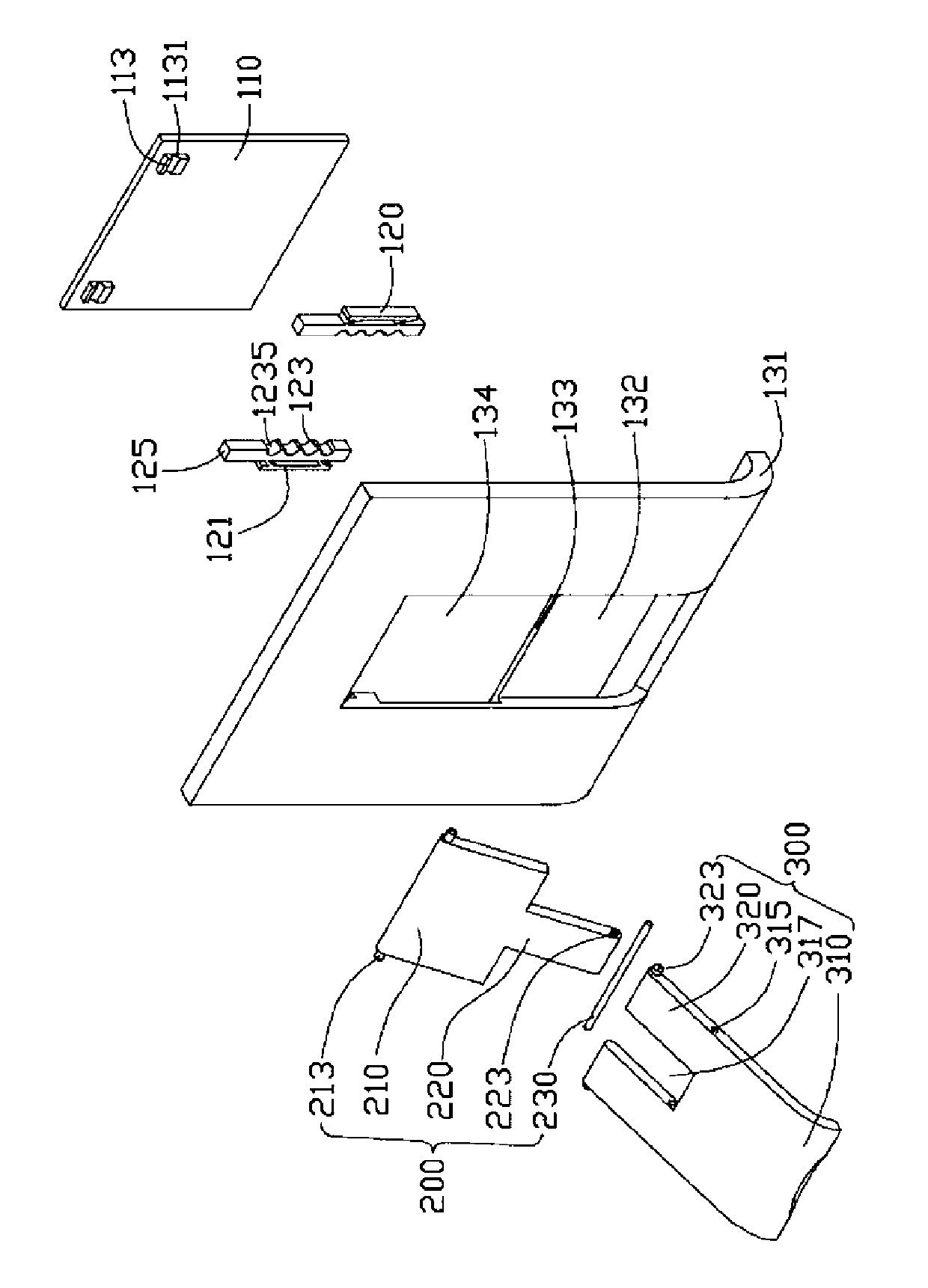
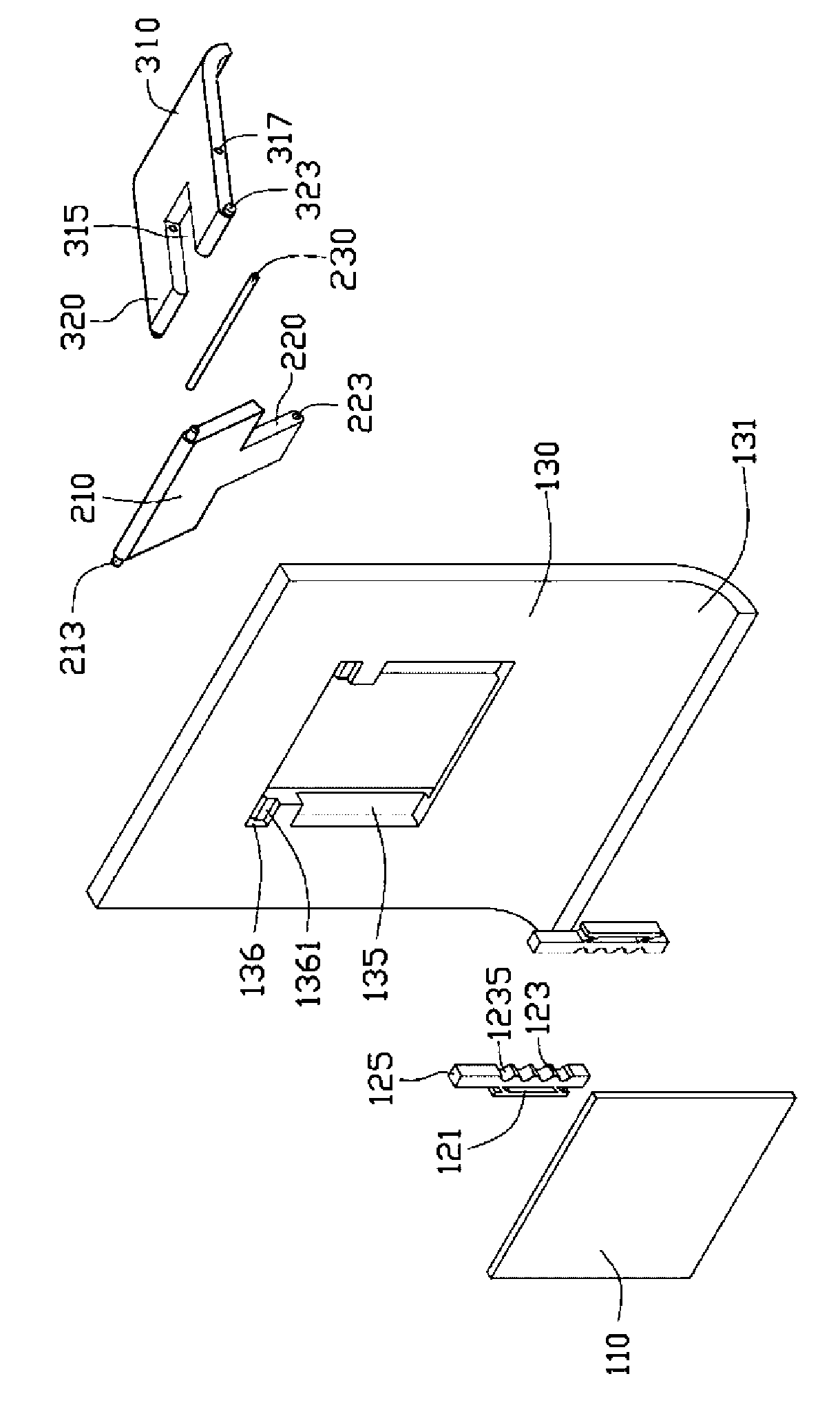
[0013] Please also refer to figure 2 and image 3 , the fixing assembly 100 includes a limiting plate 110 , a positioning member 120 and a fixing plate 130 . Wherein, the limiting plate 110 is fixed on the fixing plate 130 , and the positioning member 120 is fixed between the limiting plate 110 and the fixing plate 130 .

[0014] The limiting plate 110 is roughly a rectangular plate with two protruding positioning portions 113 on its top. The two positioning portions 113 are opposite to the fixing plate 130 , and the middle portions thereof are respectively indented to form first grooves 1131 . The cross-section of the first groove 1131 is substantially arc-shaped.

[0015] The fixing plate 130 is opposite to the limiting plate 110 , and the middle portion of the surface ...


PUM


Abstract

The invention relates to a bracket. The bracket comprises a fixing assembly, a pivotable member and a supporting member, wherein the fixing assembly is provided with a plurality of slots and a first accommodating part; two opposite ends of the pivotable member are respectively and rotatably connected with the fixing assembly and the supporting member; one end of the supporting member is slidably arranged into the slot; a certain angle is formed by the pivotable member and a supporting plate; the supporting member moves in the slots; and the pivotable member can rotate around the supporting plate to change an included angle between the pivotable member and the supporting member and an included angle between the supporting member and the fixing assembly so as to achieve the purpose of adjusting the supporting angle, therefore, a user can adjust a viewing angle as required.

Description

technical field [0001] The invention relates to a bracket, in particular to a bracket for supporting portable electronic equipment. Background technique [0002] At present, devices such as photo frames and PDAs all have a main body and legs supported on the rear surface of the main body. The legs are rotatably fixed on the main body. In this way, a triangular support structure is formed by the main body, the supporting legs and the bearing. The stand includes a stopper, and the stopper is used to limit the rotation angle of the stand relative to the main body. When in use, the supporting legs are rotated, and when the stopper part abuts against the main body, the supporting legs stop rotating and are supported on the desktop. [0003] However, the above-mentioned supporting legs can only support the main body at a specific angle, and the user cannot adjust the supporting angle according to specific needs so as to adjust the viewing angle. Contents of the invention [...

Claims


Application Information

Patent Timeline
IPC IPC(8): F16M11/00
Inventor 蒋斌李德华王满中
Owner HONG FU JIN PRECISION IND (SHENZHEN) CO LTD
Why Eureka
Try Eureka