
Manufacturing method of blade for centrifugal aeration blower diffuser and positioning tool for same
A manufacturing method and a technology for positioning tooling, applied in positioning devices, manufacturing tools, metal processing equipment, etc., can solve problems affecting the positioning accuracy of tooling, blades exceeding the assembly gap, roughness and parallelism cannot be guaranteed, and improve processing efficiency , Guarantee the effect of pass rate
- Summary
- Abstract
- Description
- Claims
- Application Information
AI Technical Summary
Problems solved by technology
Method used
Image

Examples
Embodiment 1
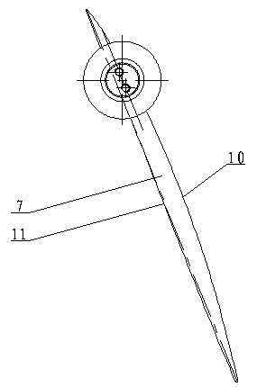
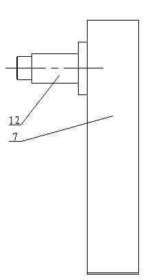
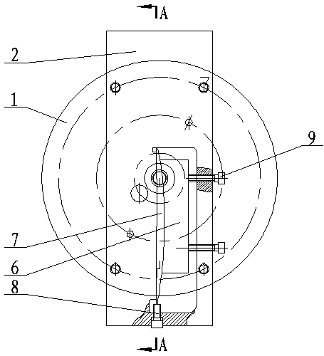
[0020] Embodiment 1: as figure 1 , 2 As shown, a method for manufacturing diffuser blades of a centrifugal aeration blower, the processing steps include: 1) Rough milling of blade squares and process straps; 2) Fine milling of blade profile; 3) Using positioning tooling , wire cutting to remove the process strap; 4), grinding the top surface of the blade; 5), using the positioning tool described in process 3), which is convenient for the lathe to turn the positioning shaft and cut off the end face of the process strap; 6), fitter repair the car Cut the flash and mill the transition radius between the two molded lines at both ends of the blade; 7) Drill the threaded bottom hole on the lathe; 8) The fitter taps the thread and deburrs; 9) Comprehensive inspection. Wherein, in the process 1), the parallelism of the blade rests is less than 0.05 mm.
[0021] In the present invention, process 1) is used as a reference when performing rough milling of the four sides of the blade an...
PUM
 Abstract
Description
Claims
Application Information