Safety burning torch with vertical movement type push button

A safety point and mobile technology, applied in the field of safety point guns, can solve the problems of triggering the safety distance and losing the function of safety, so as to achieve the effect of improving safety performance

Active Publication Date: 2014-08-06
XINHAI TECH GRP CO LTD
View PDF9 Cites 0 Cited by
  • Summary
  • Abstract
  • Description
  • Claims
  • Application Information

AI Technical Summary

Problems solved by technology

[0002] There is a safety ignition gun with a movable pressing handle. The inner wall of the pressing hand is provided with a piezoelectric working part that is convex and dislocated with the upper end surface of the piezoelectric under normal conditions. There is a gap between the inner wall of the pressing hand and the upper end surface of the piezoelectric When the pressing hand is pressed down, the piezoelectric can not excite the safe distance of high-voltage electricity. When using it, a push button needs to be pressed inward to move the pressing hand until the piezoelectric working part on the pressing hand is located on the upper end surface of the piezoelectric. Directly above, the ignition gun is in the disarmed state. At this time, when the pressing hand is pressed down, the pressing hand completes the stroke, makes the piezoelectric work, and stimulates a high-voltage electric spark. At the same time, the pry plate opens the air outlet valve, so that the ignition gun generates flame
The above-mentioned safety ignition gun must be pressed at the same time to press the push button and press the hand to ignite, which can play a certain role in insurance. However, when children and mentally handicapped are playing, they often hold the ignition gun. If the push button touches the palm of the hand On the surface, when you hold it hard, the push button is pressed inward, and it is in the state of releasing the insurance, which also loses the function of insurance

Method used


Image

  • Safety burning torch with vertical movement type push button
  • Safety burning torch with vertical movement type push button
  • Safety burning torch with vertical movement type push button

Examples


Embodiment 1

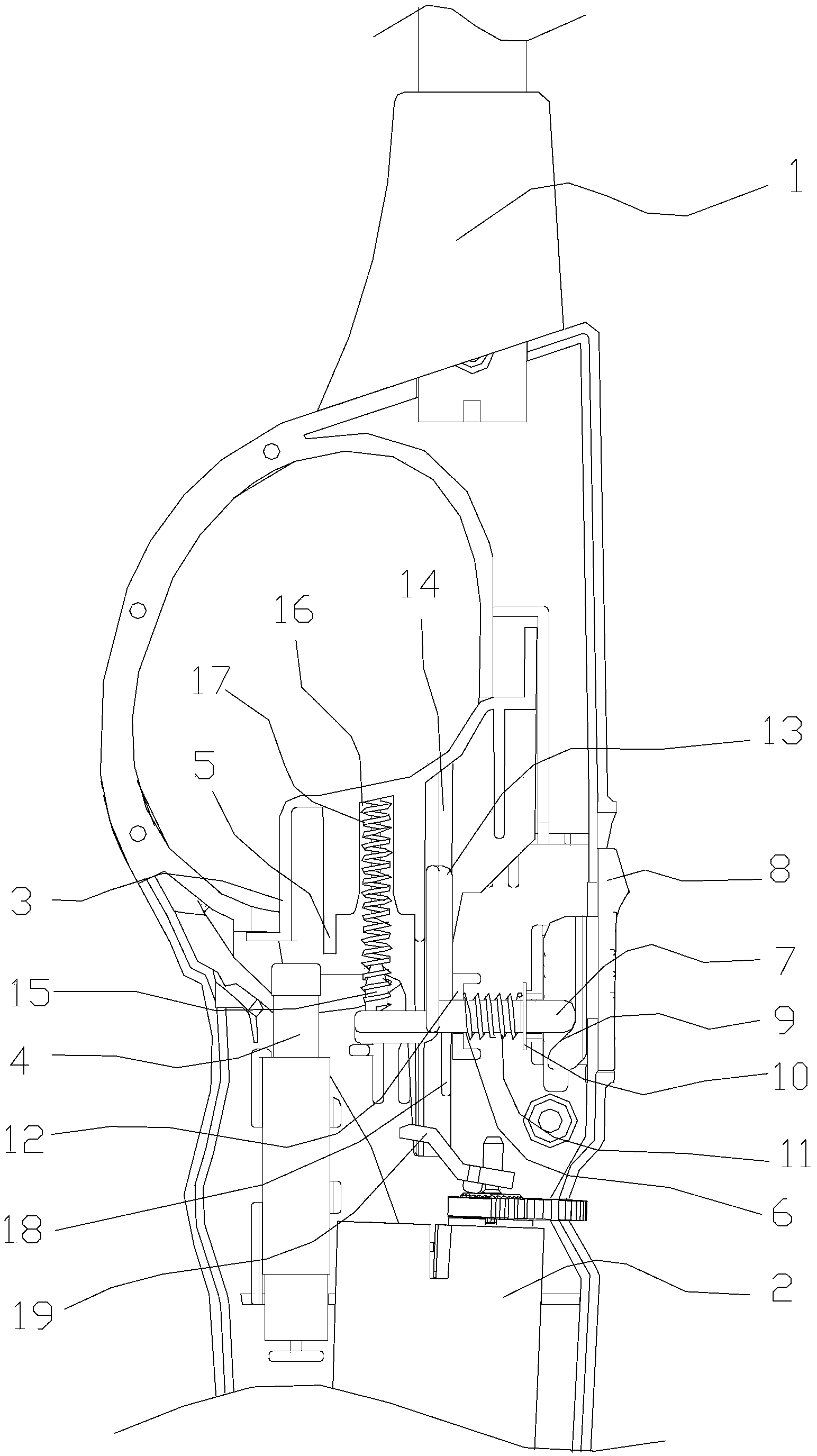
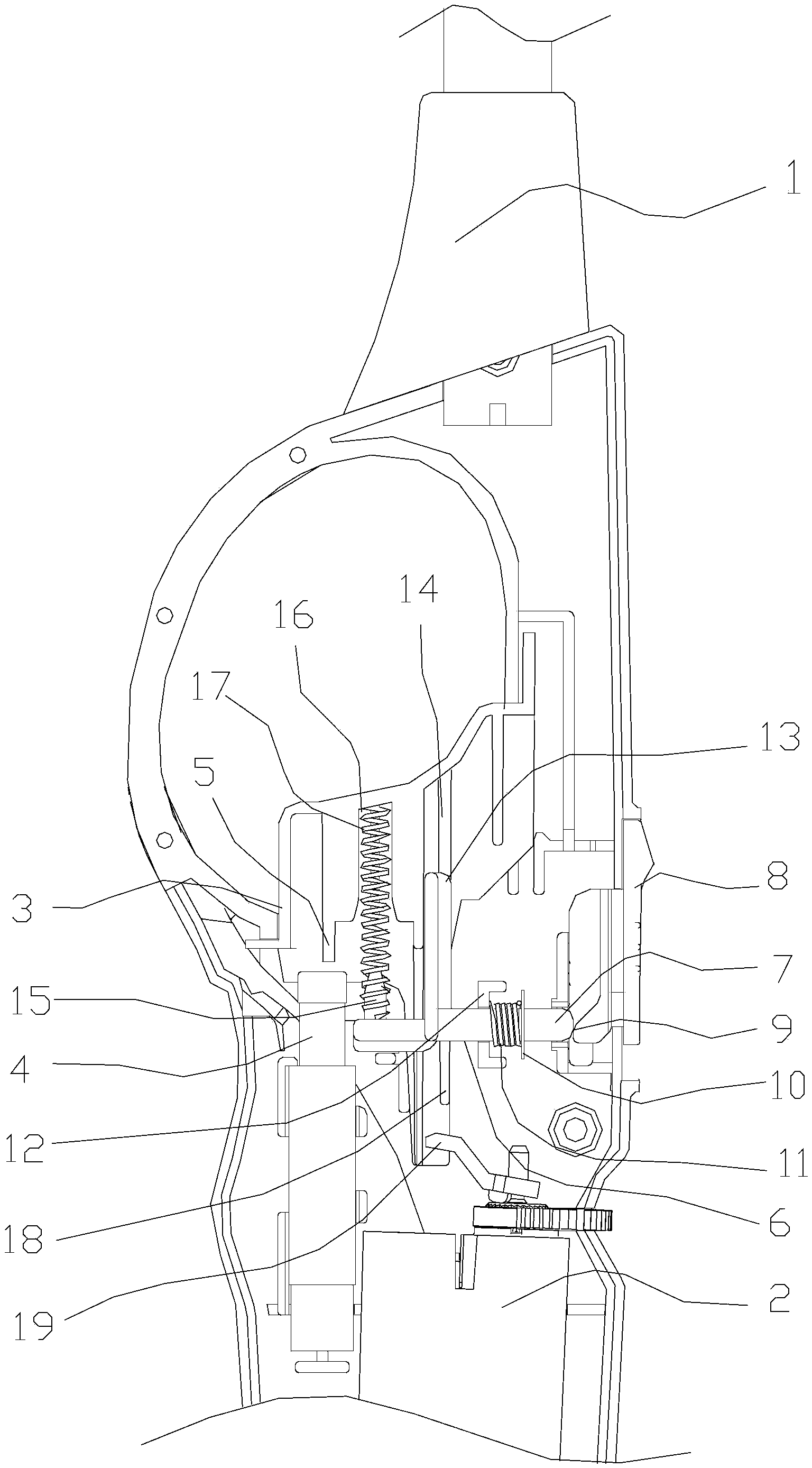
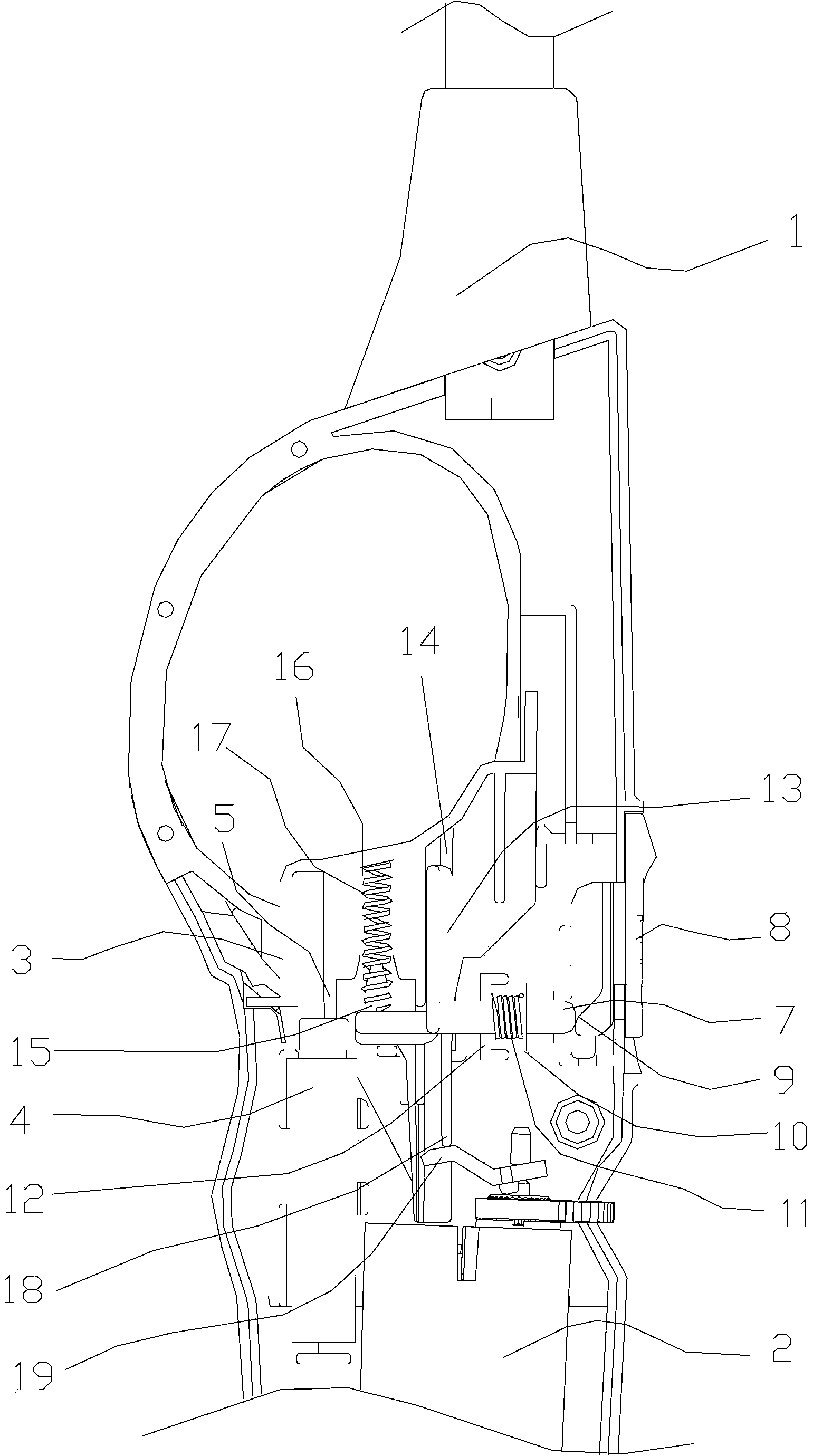
[0020] Such as Figure 1-3 As shown, a safety ignition gun with an up and down movable push button described in this embodiment includes a gun body 1, an oil tank 2 placed in the gun body, a crowbar 19 and a piezoelectric 4 installed on the oil tank, and the gun body 1 A vertically slidable pressing hand 3 is installed on the top, and the inner wall of the pressing hand 3 forms a convex working part 5 which is dislocated with the upper end of the piezoelectric under normal conditions. The inner wall of the pressing hand 3 and the upper end surface of the piezoelectric 4 There is a safe distance between the pressing hand 3 and a slide block 6 that makes it move laterally when the pressing hand is pressed down under normal conditions, and the piezoelectricity cannot be excited to generate high-voltage electricity. The push button end of slide block 6 forms a transverse part 7, and the outside of described transverse part 7 is provided with a push button 8 that can shift up and d...


PUM


Abstract

The invention designs a safety burning torch with a vertical movement type push button. By using the safety burning torch, the technical problems that a push button of a conventional safety burning torch is in inwards pressed-in mode and the mis-operation is easily performed are solved. The safety burning torch comprises a torch body, an oil groove, a prying plate and piezoelectricity; the oil groove is arranged in the torch body; the prying plate is mounted on the oil groove; a pressing handle capable of vertically sliding is mounted on the torch body; and a piezoelectric working part which is downwards convex, and furthermore, is arranged in a way of being staggered with the upper end part of the piezoelectricity in an ordinary state is formed on the inner wall of the pressing handle. The safety burning torch is characterized in that the pressing handle is matched with a sliding block enabling the pressing handle to transversely move; a transverse part is formed at the end of the sliding block, which approaches the push button; the push button which can vertically shift is arranged at the outer side of the transverse part; furthermore, the outer half part of the push button is positioned outside the torch body; and an oblique plane for pushing the sliding block to move is arranged at the lower end of the inner half part of the push button. According to the safety burning torch, the pressed button is changed into the vertical movement type button; accidents such as a fire disaster and the like, caused by the mis-operation of a child and a retardate, can be prevented; and the safety performance of the burning torch is further promoted.

Description

technical field [0001] The invention relates to the field of safety ignition guns, in particular to an safety ignition gun with a vertically movable push button. Background technique [0002] There is a safety ignition gun with a movable pressing handle. The inner wall of the pressing hand is provided with a piezoelectric working part that is convex and dislocated with the upper end surface of the piezoelectric under normal conditions. There is a gap between the inner wall of the pressing hand and the upper end surface of the piezoelectric When the pressing hand is pressed down, it is impossible to make the piezoelectric excite the safe distance of high-voltage electricity. When using it, you need to press a push button inward to move the pressing hand until the piezoelectric working part on the pressing hand is located on the upper end surface of the piezoelectric. Directly above, the ignition gun is in the disarmed state. At this time, when the pressing hand is pressed dow...

Claims


Application Information

Patent Timeline
Patent Type & Authority Patents(China)
IPC IPC(8): F23Q2/28F23Q2/34
Inventor 黄新华朱张和
Owner XINHAI TECH GRP CO LTD
Why Eureka
Try Eureka