Hull without stern cover and unbalanced rudder blade

A stern seal and unbalanced technology, which is applied to the hull, hull parts, rudder steering, etc., can solve the problems of increased scissors gap and reduced rudder effect, so as to improve maneuverability, improve rudder effect, and improve rudder efficiency. effective effect

Inactive Publication Date: 2015-09-23
JIANGSU UNIV OF SCI & TECH
View PDF6 Cites 0 Cited by
  • Summary
  • Abstract
  • Description
  • Claims
  • Application Information

AI Technical Summary

Problems solved by technology

However, this favorable factor can only be better reflected when the hull where the rudder blades are installed is flat. The leaf is a mechanism that can rotate around the center of the rudder stock, so the existing technology can only make the upper edge of the rudder and the bottom plate of the hull have a good coincidence state (that is, the gap is the smallest) at a certain corner of the rudder blade, so that the The rudder blade has a better rudder effect at this turning angle
For example, for a single-stern and single-rudder ship, at a rudder angle of 0°, the shape of the upper edge of the rudder blade can be parallel to the shape of the stern bottom plate and the gap can be minimized, so that the rudder effect is the best at this time, but when the rudder turns At a certain angle, in order to prevent the rudder blade from colliding with the hull or due to the shape of the hull itself, the parallel and close relationship between the shape of the upper edge of the rudder blade and the shape of the bottom plate of the hull must be lost. At this time, the gap becomes a scissors difference. reducing the rudder efficiency

Method used


Image

  • Hull without stern cover and unbalanced rudder blade
  • Hull without stern cover and unbalanced rudder blade
  • Hull without stern cover and unbalanced rudder blade

Examples


Embodiment Construction

[0015] The present invention will be further described below in conjunction with the accompanying drawings and specific embodiments.

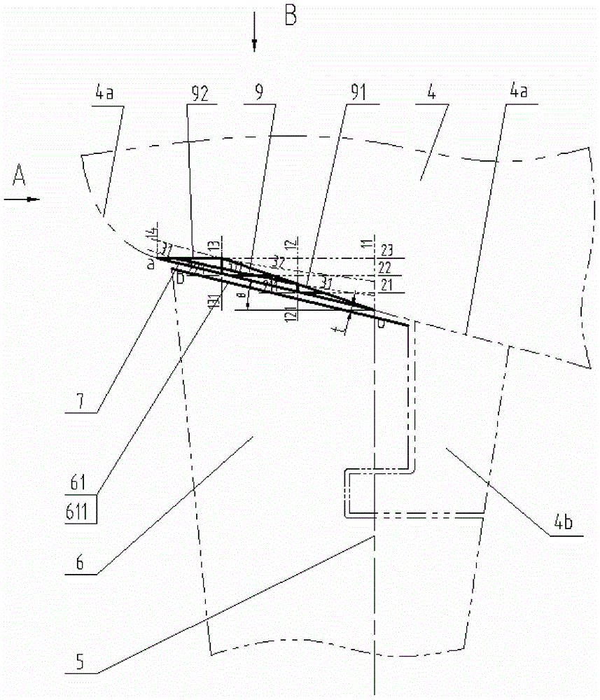
[0016] figure 1 It is a side view (straight sectional view) of the present invention, showing the relative position of the rudder and the hull when part of the straight section line and the rudder are at a rudder angle of 0°;

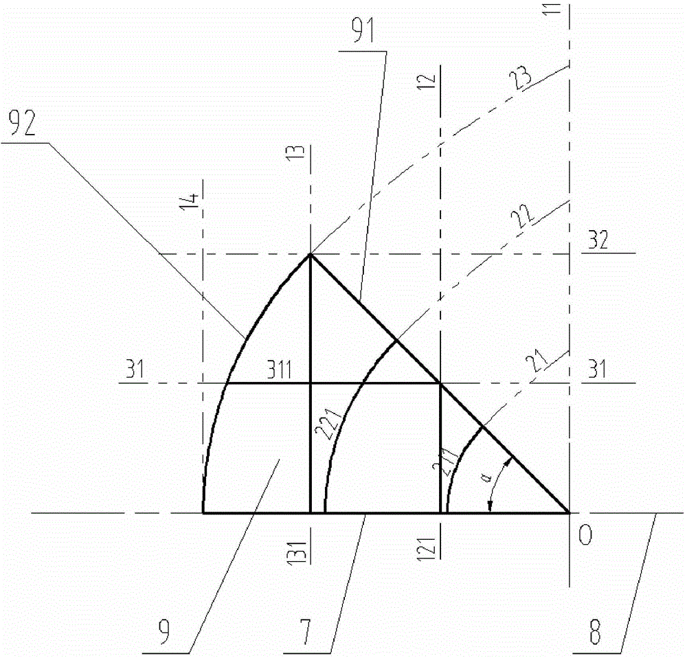
[0017] figure 2 It is the A-direction view (station plan) of the present invention, due to symmetry, only part of the molded line on the port side is shown;

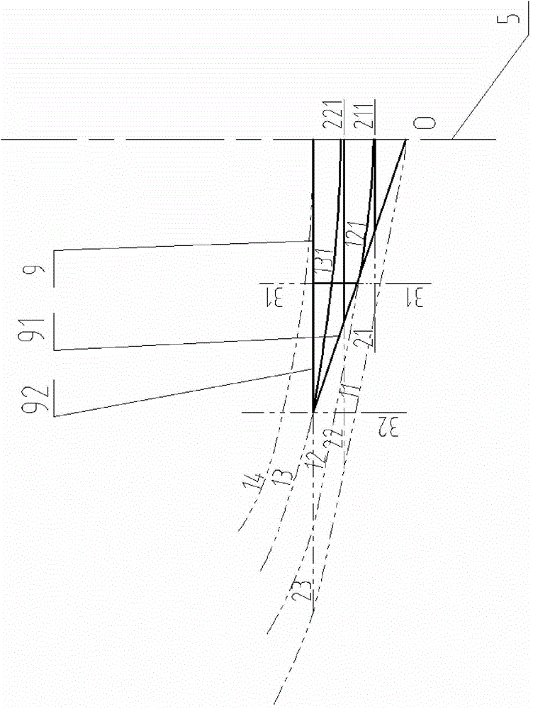
[0018] image 3 It is a B-direction view (waterline view) of the present invention. Due to symmetry, only part of the molded line on the port side is shown.

[0019] During specific implementation, obtain a satisfactory hull shape line according to the following steps. like figure 1 As shown, the curve segment oa is intercepted on the 0° straight profile line 4a of the hull as the generatrix 7 of the hull spiral surface.

[0020] 1. Taking the busbar 7 of th...


PUM


Abstract

The invention discloses a non-stern transom plate ship and a rudder blade of an unbalanced rudder. The shape at the bottom of the ship where the ship rudder blade is installed is a tapered ship spiral curved surface. Within an angle rotation range of the rudder blade, for a streamlined rudder, the upper end face of the rudder blade is a curved surface parallel to the ship spiral curved surface. For a flat rudder, an upper end line of the rudder blade is a curved line parallel to the ship spiral curved surface. Characteristics of ship molded lines, rudder blade molded lines, neck bearing structures and the like are considered sufficiently, and the non-stern transom plate ship and the rudder blade of the unbalanced rudder are used for installation of various non-stern transom plates and single-rudder ships or multi-rudder ships with semi-balanced or unbalanced rudders. Within the angle rotation range of the rudder blade, the shape of the upper edge of the rudder blade is always parallel to the shape of a ship bottom plate so as to enable gaps to be minimum, the shape of the upper edge of the rudder blade and the shape of the ship bottom plate always keep best spatial coordination, rudder effect is improved effectively, the rudder effect can be improved by above one time, maneuverability of the ship is improved, and energy is saved.

Description

technical field [0001] The invention relates to a hull and rudder blades, in particular to a hull without a stern seal and an unbalanced rudder blade, which are suitable for various types of ships without a stern seal equipped with semi-balanced or unbalanced rudders, and belong to the technical field of ships. Background technique [0002] The maneuverability of the ship plays an important role in the overall performance of the ship and the quality of the ship's navigation performance, and the rudder plays a decisive role in the maneuverability of the ship. Therefore, how to improve the rudder efficiency has become one of the important issues studied by shipbuilders. It has long been recognized theoretically that the aspect ratio plays a decisive role in the rudder effect under the condition that the rudder area and rudder section remain unchanged. . However, due to the limitation of the ship's draft and waterway, the aspect ratio of the general ship is small, especially t...

Claims


Application Information

Patent Timeline
Patent Type & Authority Patents(China)
IPC IPC(8): B63B3/14B63H25/38
Inventor 周玉龙赵鹏王志东
Owner JIANGSU UNIV OF SCI & TECH
Why Eureka
Try Eureka