Electronic device protection sleeve

A technology for electronic devices and protective covers, applied in circuit devices, battery circuit devices, circuits, etc., can solve problems such as user fatigue, users cannot adjust the angle of use of electronic devices, and cannot adjust the angle of use of electronic devices.

Active Publication Date: 2013-05-08
FU TAI HUA IND SHENZHEN +1
View PDF7 Cites 7 Cited by
  • Summary
  • Abstract
  • Description
  • Claims
  • Application Information

AI Technical Summary

Problems solved by technology

[0002] At present, some electronic devices are provided with coils in the protective cases, and the electronic devices are wirelessly charged by placing the part of the protective case provided with the induction coil on the charging stand, but since the protective case is only equipped with an induction coil The coil is in a fixed position, so when charging the electronic device through the protective cover, when the user wants to use the electronic device at the same time, the electronic device can only be used at a fixed angle, and the use angle of the electronic device cannot be adjusted , For example, the induction coil of the general protective cover is set on the back. When charging, the back needs to be placed flat on the charging stand. When the user uses the electronic device, he can only use it in a overlooking way. Fatigue, and the user cannot adjust the angle of use of the electronic device according to his own preferences

Method used


Image

  • Electronic device protection sleeve
  • Electronic device protection sleeve
  • Electronic device protection sleeve

Examples


Embodiment Construction

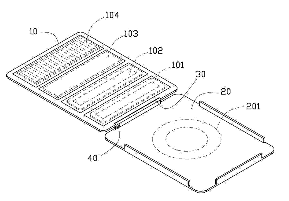
[0014] like figure 1 As shown, it is a perspective view of an electronic device protective cover 1 . The protective cover 1 includes an upper cover 10 and a lower cover 20 , and the upper cover 10 and the lower cover 20 are connected together by a hinge 30 . The protective cover 1 further includes an interface 40 for electrically connecting an electronic device (not shown). The lower cover 20 is covered with a first induction coil 201 , and the first induction coil 201 is electrically connected to the interface 40 .

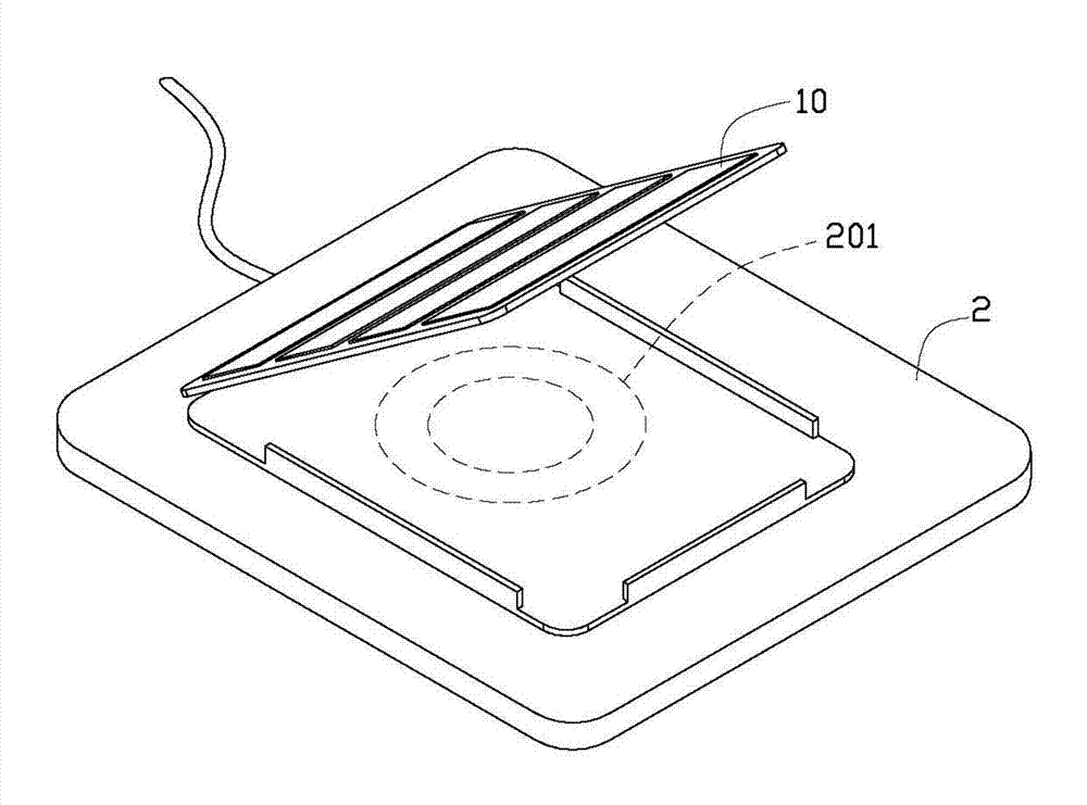
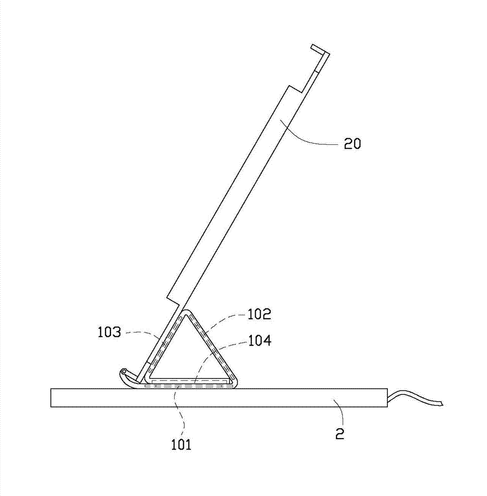
[0015] like figure 2 As shown, the lower cover 20 is placed on a charging base 2 with a main coil (not shown) to charge the electronic device connected to the protective cover 1 .

[0016] The upper cover 10 covers a second induction coil 101 , a third induction coil 102 , a battery 103 , and a solar panel 104 . The second induction coil 101 and the third induction coil 102 are connected to the interface 40 and connected to the battery 103 at the same time. ...


PUM


Abstract

The invention provides an electronic device protection sleeve. The protection sleeve comprises an upper cover and a lower cover, the upper cover is hinged to the lower cover through a hinge, the protection sleeve also comprises an interface, the interface is used for the electric connection with an electronic device, the lower cover is coated with a first induction coil, the first induction coil is in electric connection with the interface, the lower cover is arranged on a charging socket having a main coil to charge the electronic device connected to the protection sleeve, the upper cover is transversely divided into at least three parts, each two parts of the at least parts are folded to a certain angle, at least one second induction coil is coated in the at least three parts, and the at least second induction is in electric connection to the interface.

Description

technical field [0001] The invention relates to a protective cover for electronic devices, in particular to a protective cover for wirelessly charging electronic devices. Background technique [0002] At present, the protective cover of some electronic devices is provided with a coil, and the electronic device is wirelessly charged by placing the part of the protective cover provided with the induction coil on the charging base, but since there is only one induction coil on the protective cover during charging The coil is in a fixed position, so when charging the electronic device through the protective cover, when the user wants to use the electronic device at the same time, the electronic device can only be used at a fixed angle, and the use angle of the electronic device cannot be adjusted. , For example, the induction coil of the general protective cover is set on the back. When charging, the back needs to be placed on the charging stand. When using the electronic device...

Claims


Application Information

Patent Timeline
Patent Type & Authority Applications(China)
IPC IPC(8): A45C15/00H02J17/00H02J7/00
CPCH01M10/465Y02E60/10
Inventor 吴金忠
Owner FU TAI HUA IND SHENZHEN
Why Eureka
Try Eureka