An optimized cable laying system for multiplexed 2m protection channels in substations

A technology for protecting channels and substations, applied in substation/switch layout details, electrical components, busbar/line layout, etc., can solve the problems of optical cable laying, heavy welding workload, low construction efficiency, and many cable channel transfers, etc., to achieve The effect of reducing the workload of optical cable laying, improving the overall reliability, and simplifying the workload of operation and maintenance

Active Publication Date: 2017-02-22
ZHEJIANG ELECTRIC POWER DESIGN INST
View PDF6 Cites 0 Cited by
  • Summary
  • Abstract
  • Description
  • Claims
  • Application Information

AI Technical Summary

Problems solved by technology

[0004] 1) There are a large number of protective optical cables, and the workload of optical cable laying and welding is large, resulting in low construction efficiency;
[0005] 2) There are many cable channel transfers, and the operation and maintenance interfaces of the protection and communication professions are unclear, which is not conducive to rapid troubleshooting;
[0006] 3) The protection equipment is constructed in stages, resulting in the laying of the protection optical cables in stages, requiring repeated work such as uncovering the cable cover plate and sealing the cable trench for fire prevention, which reduces the overall reliability of the optical cable line;
[0007] 4) There are too many protective optical cables laid in the cable trench, and the requirements for safety measures such as fire prevention in the cable trench are relatively high

Method used


Image

  • An optimized cable laying system for multiplexed 2m protection channels in substations
  • An optimized cable laying system for multiplexed 2m protection channels in substations
  • An optimized cable laying system for multiplexed 2m protection channels in substations

Examples


Embodiment Construction

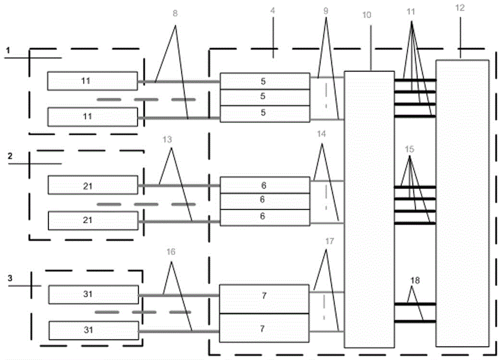
[0017] Take the final output scale of a 500kV substation as an example: 10 circuits for 500kV lines and 12 circuits for 220kV lines. The 500kV line is equipped with 2 sets of protection for each circuit, and each set of protection multiplexes 2 2M channels. Each 220kV line is equipped with 2 sets of protection, 1 set of dedicated fiber core, and 1 set of multiplexing 2M. Based on the above case, the 500kV substation is considered to be based on the final scale of 52 sets of multiplexing 2M protection, the length of the optical cable from the relay room to the communication room is considered as 200 meters, the length of the 2M cable connection between the screens is considered as 10 meters, and the length of the 2M cable connection in the screen is uniform Consider 2 meters.

[0018] Such as figure 1 As shown, the schematic diagram of cable connection in the traditional multiplexing 2M protection channel station includes 500kV relay room I1, 500kV relay room II2, 220kV relay...


PUM


Abstract

The invention discloses an optimal laying system for a substation multiplexing 2M protection channel cable. The system comprises a relay room, a communication machine room, a multiplexing protection interface cabinet, a protection optical cable, a relay room protection optical fiber distribution frame, a communication machine room protection optical fiber distribution frame, a tail fiber, a 2M large cable, optical transmission equipment and a line protection device, wherein the relay room comprises the line protection device, the tail fiber and the relay room protection optical fiber distribution frame; the line protection device in the relay room is connected into the relay room protection optical fiber distribution frame through the tail fiber; the relay room protection optical fiber distribution frame is connected into the communication machine room protection optical fiber distribution frame through the protection optical cable. According to the system, the integral reliability of the multiplexing 2M protection channel cable is improved, the interface of the protection specialty and the communication specialty is cleared, the operation and maintenance workload is simplified, the laying workload of the cable is reduced, and the characteristics of science, rationality, reliability and the like are realized.

Description

technical field [0001] The invention relates to a substation multiplexed 2M protection channel cable laying optimization system, which belongs to the optical cable network system of the electric power communication network. Background technique [0002] With the development of optical fiber communication and relay protection technology, multiplexing 2M protection based on optical fiber communication has been widely used in power grids. The method of multiplexing 2M protection channels in substations means that the protection devices in the substation pass through a pair of optical fiber transceiver devices, and the protection signals are converted into 2M electrical signals by the photoelectric conversion device (O / E device) in the multiplexing interface cabinet and then communicated. The digital distribution frame is connected to the SDH optical transceiver for communication, and the SDH transmission channel is used to complete the 2M electrical signal transmission. With t...

Claims


Application Information

Patent Timeline
Patent Type & Authority Patents(China)
IPC IPC(8): H02B1/20G02B6/44
CPCG02B6/4452H02B1/20H02B1/202
Inventor 方祥雷方显业胡映梅赵萌刘宏波李慧毛婕陈北海郑雅敏李亚雷
Owner ZHEJIANG ELECTRIC POWER DESIGN INST
Why Eureka
Try Eureka