Electronic kitchen timer

A timer and electronic technology, applied in the application field of electronic technology, can solve problems such as insufficient operation

Inactive Publication Date: 2016-09-28
黄月华
View PDF6 Cites 0 Cited by
  • Summary
  • Abstract
  • Description
  • Claims
  • Application Information

AI Technical Summary

Problems solved by technology

Its disadvantages are: one is that it needs to be powered by batterie

Method used


Image

  • Electronic kitchen timer

Examples


Embodiment Construction

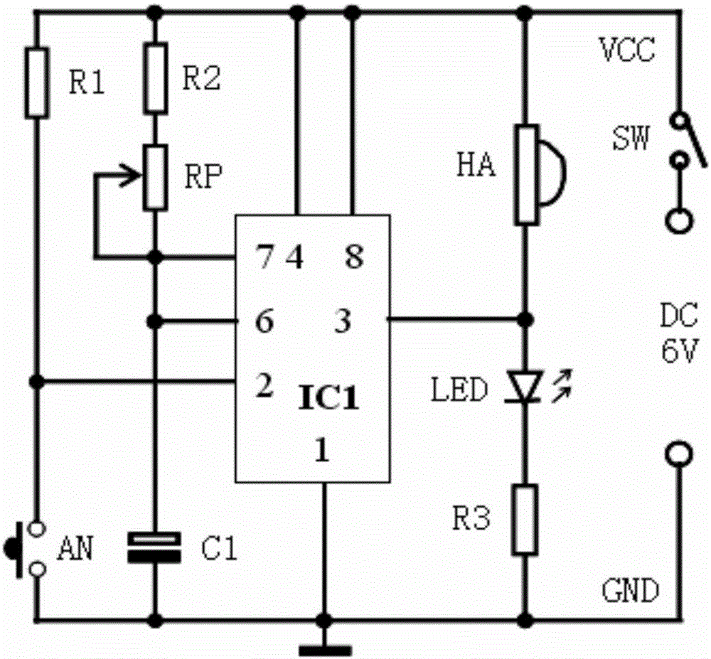
[0013] According to attached figure 1 The working principle diagram and accompanying drawings of the kitchen electronic timer circuit are shown, and the connection relationship between the components in each part of the circuit described in the summary of the invention, as well as the technical parameter requirements of the components and the circuit described in the implementation mode The present invention can be realized by making the main points and carrying out implementation. The related technologies of the present invention will be further described below in conjunction with the embodiments.

[0014] Technical parameters of components and their selection requirements

[0015] IC1 is the time base circuit, the selected model is: NE555; the package form of NE555 integrated circuit is DIP, the function of each pin: the first pin is the circuit ground; the second pin is the trigger end; the third pin is the output end; the fourth pin is Reset terminal; pin 5 is the control...


PUM


Abstract

The invention provides an electronic kitchen timer. The electronic kitchen timer is characterized by comprising a 6V DC power source, a mono-stable timing circuit, a start circuit, a buzzer and a state indication circuit, wherein models of the mono-stable timing circuit and a time-base circuit IC1 of the start circuit are NE555. An electronic mode is advantaged in that timing accuracy is high, and alarm sound is load, disadvantages of the electronic mode are that cells are utilized for power supply, and operation during use is not concise enough. For solving practical problems of the electronic mode, one time-base circuit is taken as a core element, the time-base circuit is made to be a mono-stable circuit, periphery utilizes a few of components, and operation rapidness is realized.

Description

technical field [0001] The invention belongs to the application field of electronic technology, and relates to an electronic timer for kitchen. Background technique [0002] There are two main types of timers commonly used in the kitchen, one is to use mechanical timing; the other is to use electronic timing. The advantages of the mechanical timer: one is that it does not use batteries; the other is that it is easy to operate and use. Its defects are: the timing is not accurate enough, the alarm time is short and the alarm sound is relatively small. The advantages of the electronic timer: First, the timing accuracy is high; second, the alarm sound is loud. Its defect is: the one, circuit structure is complicated; Two, needs to use battery to power it for it; [0003] In order to effectively solve the practical problems of electronic timing, this invention uses a time base circuit as the core component, and connects it into a monostable circuit. Only a small number of comp...

Claims


Application Information

Patent Timeline
IPC IPC(8): G04G13/02G04G19/00
CPCG04G13/021G04G19/00
Inventor 黄月华
Owner 黄月华
Why Eureka
Try Eureka