Mobile phone connecting equipment

A technology for connecting devices and mobile phones, applied in the direction of connection, parts of the connection device, connection/disconnection of the connection device, etc., can solve the problems of no self-locking structure, wear and tear of the charging line, and long charging line, so as to improve work efficiency and The effect of safety, improving work efficiency and simple structure

Inactive Publication Date: 2017-08-08
福州和信城电子科技有限公司
View PDF5 Cites 0 Cited by
  • Summary
  • Abstract
  • Description
  • Claims
  • Application Information

AI Technical Summary

Problems solved by technology

However, the existing mobile phone charging device is relatively simple to set up, and its charging line is long and leaks, which will easily cause the charging line to be worn, which shortens the service life and seriously affects the appearance. At the same time, the charging head is a fragile object. The bottom is still exposed to the outside world, which increases the probability of damage; the existing mobile phone charging device does not have a self-locking structure, and the mobile phone is easy to loose from the socket and cause losses.

Method used


Image

  • Mobile phone connecting equipment
  • Mobile phone connecting equipment
  • Mobile phone connecting equipment

Examples


Embodiment Construction

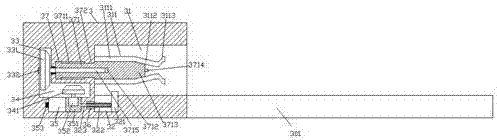
[0025] like Figure 1-Figure 6 As shown, a mobile phone connection device of the present invention includes a mobile phone socket 2 and a mobile phone 4, and is characterized in that: a cavity 31 is provided in the right end surface of the mobile phone socket 2, and a cavity 31 is provided in the right end surface of the mobile phone socket 2. The vertical slot 22 extending downwards, the cavity 31 is provided with a power supply device 3, and the right end surface of the power supply device 3 is provided with an insertion horizontal groove 31, and the left side of the insertion horizontal groove 31 The power feeding device 3 is provided with a first sliding groove 37, the power feeding device 3 on the left side of the first sliding groove 37 is provided with a first wheel chamber 33, and all the parts below the first sliding groove 37 are The power feeding device 3 is provided with a second wheel chamber 34 whose left end is connected to the bottom of the first wheel chamber ...


PUM


Abstract

The invention discloses mobile phone connecting equipment. The mobile phone connecting equipment comprises a mobile phone socket and a mobile phone; an accommodating cavity is formed in the right side end plane of the mobile phone socket; a vertical groove which extends downwards is formed in the right side end plane of the mobile phone socket; a power supplying apparatus is arranged in the accommodating cavity; an inserting-combining transverse groove is formed in the right side end plane of the power supplying apparatus; a first sliding groove is formed in the power supplying apparatus on the left side of the inserting-combining transverse groove; a first wheel cavity is formed in the power supplying apparatus on the left side of the first sliding groove; a second wheel cavity, the left side end of which is connected with the bottom of the first wheel cavity, is formed in the power supplying apparatus below the first sliding groove; elastic strips are correspondingly and fixedly arranged on the upper and lower parts of the inner wall on the left side of the inserting-combining transverse groove; a power supplying push rod which extends towards the right side is arranged in the first sliding groove; and the right side extension section of the power supplying push rod extends into the inserting-combining transverse groove. The mobile phone connecting equipment is simple in structure, convenient to operate, capable of automatically controlling driving, locking and connecting while completing automatic charging and power supplying connection when the mobile phone is inserted for charging, so that working efficiency and safety are improved.

Description

technical field [0001] The invention relates to the technical field of mobile phones, in particular to a mobile phone connection device. Background technique [0002] With the continuous progress of society, there are more and more convenience measures. Mobile phone charging devices are installed in some public places such as stations, shopping malls, hospitals, etc. This convenience measure has aroused high praise from the general public. However, the existing mobile phone charging device is relatively simple to set up, and its charging line is long and leaks, which will easily cause the charging line to wear out, which will shorten the service life and seriously affect the appearance. At the same time, the charging head is a fragile object. It is still exposed to the outside world, which increases the probability of damage; the existing mobile phone charging device does not have a self-locking structure, and the mobile phone is easy to loose from the socket and cause losse...

Claims


Application Information

Patent Timeline
IPC IPC(8): H01R13/627H01R13/629H01R13/635H01R13/187H01R43/26H04M1/02
CPCH01R13/627H01R13/187H01R13/629H01R13/635H01R43/26H04M1/02
Inventor 徐小风
Owner 福州和信城电子科技有限公司
Why Eureka
Try Eureka