Microhole mold for reducing burrs on punching portion

A technology for microporous molds and parts, which is applied in the direction of perforating tools, manufacturing tools, positioning devices, etc., can solve the problems of high requirements for microporous molds and affect product quality, and achieve the goal of reducing burrs, avoiding jumping and offsetting, and reducing burrs Effect

CN107234169APending Publication Date: 2017-10-10昆山钣源冲压技术有限公司
0 Cites 10 Cited by

Patent Information

Authority / Receiving Office
CN · China
Current Assignee / Owner
Publication Date
2017-10-10

Smart Images

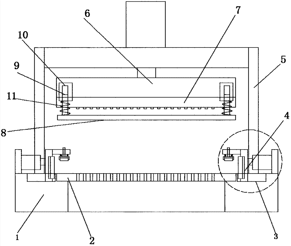
  • Figure 1
    Figure 1
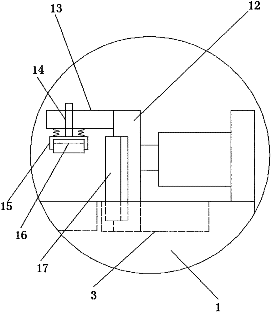
  • Figure 2
    Figure 2
Patent Text Reader

Abstract

The invention discloses a microhole mold for reducing burrs on a punching portion. The microhole mold comprises a base. A punching lower mold is mounted at the top of the base. Strip-shaped sliding grooves located on the upper surface of the base are formed in the two sides of the punching lower mold. A pressing mechanism is mounted in each sliding groove in a sliding manner. A support is mounted at the bottom of the base. An upper mold mounting plate parallel to the base is mounted on the side, close to the base, of the support. A punching upper mold is mounted on the side, close to the base, of the upper mold mounting plate. Press plates parallel to the base are mounted at the two ends of the side, close to the base, of the punching upper mold. Connecting rods are vertically mounted at the two ends of the side, away from the base, of each press plate. The end, away from the corresponding press plate, of each connecting rod is movably sleeved with a sleeve fixedly connected with the upper mold mounting plate. According to the microhole mold, bouncing deviation of a plate during punching is avoided, the plate is subjected to alignment and calibration, and therefore the burrs generated due to bouncing deviation of the plate during punching are reduced, the plate punching precision is improved, and product burrs are reduced.
Need to check novelty before this filing date? Find Prior Art

Description

technical field

[0001] The invention relates to the technical field of molds, in particular to a microporous mold for reducing burrs at punching parts. Background technique

[0002] The microporous mold is a mold used for microporous stamping of the product. Due to the small and dense arrangement of the micropores of the product, the requirements for the microporous mold are high. After the stamping is completed in the traditional microporous mold, there are A large number of burrs seriously affect the product quality, so a microporous die that reduces burrs in the punching part is needed. Contents of the invention

[0003] The purpose of the present invention is to solve the shortcomings in the prior art, and propose a microporous mold that reduces burrs in punching parts.

[0004] In order to achieve the above object, the present invention adopts the following technical solutions:

[0005] A microporous die for reducing burrs in punching parts, comprising a base, a sta...

Examples

Embodiment Construction

[0016] The following will clearly and completely describe the technical solutions in the embodiments of the present invention with reference to the accompanying drawings in the embodiments of the present invention. Obviously, the described embodiments are only some, not all, embodiments of the present invention.

[0017] refer to Figure 1-2 , a microporous die for reducing burrs in punching parts, comprising a base 1, a stamping lower die 2 is installed on the top of the base 1, and both sides of the stamping lower die 2 are provided with elongated chutes 3 on the upper surface of the base 1, The chute 3 is slidingly installed with a pressing mechanism 4, the bottom of the base 1 is equipped with a bracket 5, and the side of the bracket 5 close to the base 1 is equipped with an upper mold mounting plate 6 parallel to the base 1, and the upper mold mounting plate 6 is close to the base 1. A stamping upper die 7 is installed on one side, and a pressing plate 8 arranged parallel...