Drip infusion stand

An infusion stand and drip technology, applied in the field of medical devices, can solve problems such as inconvenience of infusion and influence on infusion.

Inactive Publication Date: 2018-01-26
GUILIN WEIMEIYUAN RESTAURANT MANAGEMENT
View PDF5 Cites 1 Cited by
  • Summary
  • Abstract
  • Description
  • Claims
  • Application Information

AI Technical Summary

Problems solved by technology

In the existing height-adjustable infusion stand, it generally stretches or shrinks two (multiple) sections of the infusion stand through screw rotation, and the thread rotation needs to rotate the infusion stand repeatedly, which will bring inconvenience to the infusion at certain times, such as when When the infusion is in progress, if the infusion stand is turned, the infusion line will be wound around the end of the infusion stand, which will drive the movement of the infusion tube and affect the progress of the infusion

Method used


Image

  • Drip infusion stand
  • Drip infusion stand
  • Drip infusion stand

Examples


Embodiment Construction

[0019] The principles and features of the present invention are described below in conjunction with the accompanying drawings, and the examples given are only used to explain the present invention, and are not intended to limit the scope of the present invention.

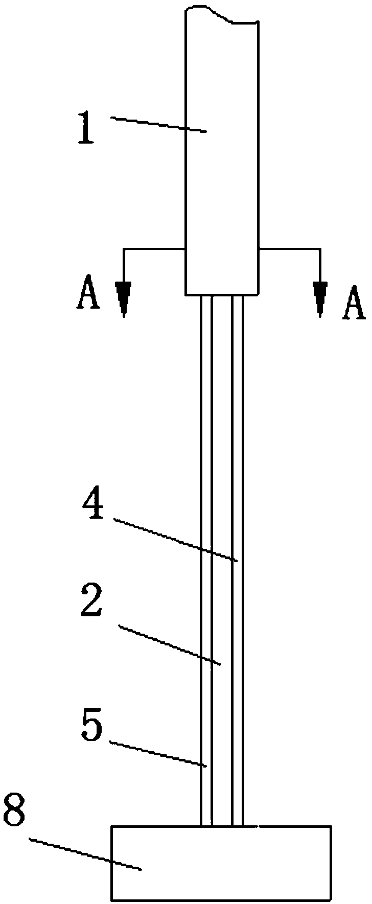
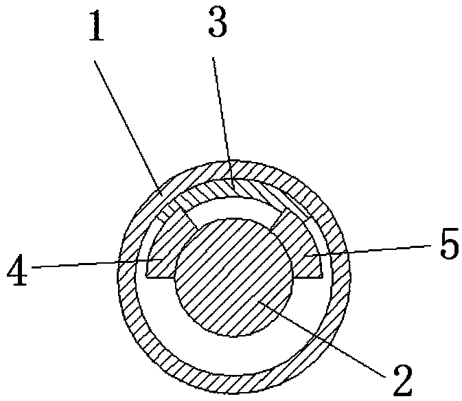
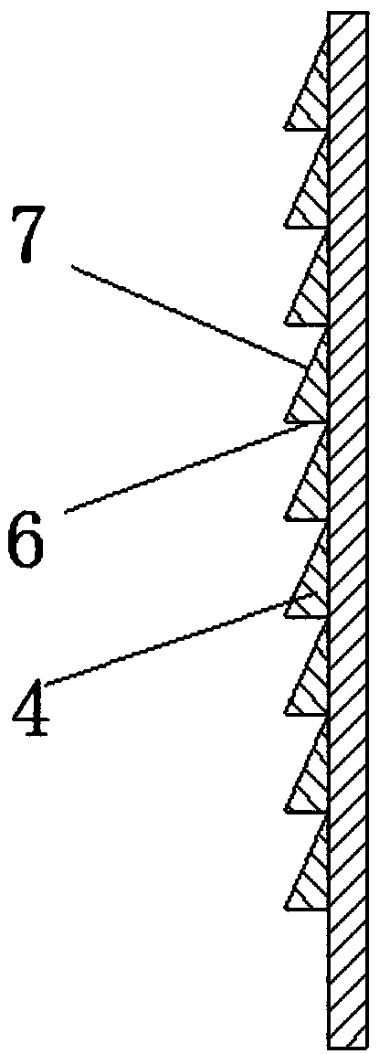
[0020] like Figure 1-4 As shown, a drip stand includes a lifting tube 1 , a column 2 and a base 8 . The column 2 is vertically fixed on the base 8 . A bracket for hanging the infusion bottle is provided on the top of the lifting tube 1 . The lifting tube 1 is sleeved on the top of the column 2 and extends vertically upward for a certain distance, and there is a gap between the lifting tube 8 and the column 2 for its relative up and down displacement; the lifting tube 1 A clamping block 3 is provided on the inner wall near one end of the column 2, and a stretching wedge strip 4 and a shrinking wedge strip 5 are horizontally provided on the side wall of the column 2 corresponding to both sides of the clamping block...


PUM


Abstract

The invention relates to a drip infusion stand, which comprises a lifting pipe and a stand column. The lifting pipe sleeves at the top part of the stand column and vertically and upwards extends to asection of distance; a clamping block is arranged on an inner wall of one end, close to the stand column, of the lifting pipe; a stretching wedge-shaped bar and a contracting wedge-shaped bar are horizontally arranged on positions, corresponding to two sides of the clamping block, on a side wall of the stand column, and comprise a plurality of wedge-shaped blocks; each wedge-shaped block comprisesa horizontal surface and an inclined surface; the inclined surfaces of the wedge-shaped blocks of the stretching wedge-shaped bar are slantways and upwards arranged toward the outer side of the standcolumn; the inclined surfaces of the wedge-shaped blocks of the contracting wedge-shaped bar are slantways and downwards arranged toward the outer side of the stand column; the stretching wedge-shaped bar and the contracting wedge-shaped bar are staggered. When the infusion stand is stretched and contracted, the lifting pipe and the stand column have no need to be oppositely and repetitively rotated and only need to be oppositely stretched or contracted horizontally, so that the occurrence of the phenomenon that the infusion stand is rotated, and an infusion pipe winds on the end part of theinfusion stand, so that the infusion pipe is driven to move so as to influence infusion is avoided.

Description

technical field [0001] The invention relates to the field of medical equipment, in particular to a drip transfusion stand. Background technique [0002] When carrying out infusion for the patient, need to use drip infusion stand. In many cases, according to the actual situation of the patient, the height of the infusion stand needs to be adjusted for better infusion. In the existing height-adjustable infusion stand, it generally stretches or shrinks two (multiple) sections of the infusion stand through thread rotation, and the thread rotation needs to rotate the infusion stand repeatedly, which will bring inconvenience to the infusion at certain times, such as when When the infusion has been carried out, if the infusion stand is rotated, the infusion pipeline will be wound around the end of the infusion stand, which will drive the movement of the infusion tube and affect the progress of the infusion. Contents of the invention [0003] In summary, in order to overcome the...

Claims


Application Information

Patent Timeline
Patent Type & Authority Applications(China)
IPC IPC(8): A61M5/14
Inventor 蒋俊
Owner GUILIN WEIMEIYUAN RESTAURANT MANAGEMENT
Why Eureka
Try Eureka