Automotive lighting device

A technology for automotive lighting and transparent components, used in signaling devices, lighting and heating equipment, vehicle components, etc., to solve problems such as unfavorable glass condensation, low flow rate, and slow defogging speed.

Active Publication Date: 2019-12-20
VALEO VISION SA
View PDF6 Cites 0 Cited by
  • Summary
  • Abstract
  • Description
  • Claims
  • Application Information

AI Technical Summary

Problems solved by technology

[0004] Therefore, the more favorable the solution is to avoid light leakage, the less favorable it is to avoid glass condensation, since

Method used


Image

  • Automotive lighting device
  • Automotive lighting device
  • Automotive lighting device

Examples


Embodiment Construction

[0039] The example embodiments are described in sufficient detail to enable one of ordinary skill in the art to embody and implement the systems and processes described herein. It is important to understand that embodiments may be provided in many alternative forms and should not be construed as limited to the examples set forth herein.

[0040] Therefore, although the embodiments may be modified in various ways and take various alternative forms, specific embodiments thereof are shown in the drawings and described in detail below as examples. There is no intention to be limited to the particular forms disclosed. On the contrary, it is intended to cover all modifications, equivalents and alternatives falling within the scope of the appended claims. Elements of the example embodiments are designated by the same reference numerals throughout the drawings and the detailed description where appropriate.

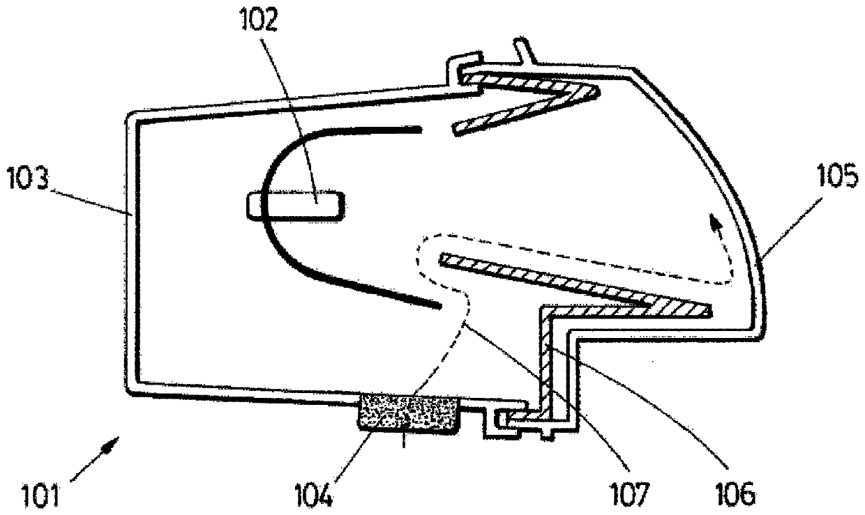
[0041] figure 1 A concept of an automotive lighting device 101 according ...


PUM


Abstract

The invention provides an automotive lighting device (1) comprising a light source (2), a housing (3) with a ventilation element (4), an outer glass (5) closing the housing (2) and an opaque element (6). The ventilation element (4) allows water vapour to pass through while preventing liquid water from entering the housing. The opaque element (6) comprises a first portion (7) located between the ventilation element (4) and the outer glass (5), wherein the first portion (7) comprises a permeable element which allows water vapour to pass through but does not allow light to pass through.

Description

technical field [0001] The present invention is in the field of lamps for motor vehicles and more particularly relates to the design of headlamps which avoid fogging of the exterior glass. Background technique [0002] Current headlamps must meet different requirements, sometimes involving conflicting design paths. One such example has to do with the problem of dehazing. [0003] Fogging is caused when water vapor condenses on the inner surface of the glass. Microdroplets are unsightly and affect light behavior, so a huge effort is required to solve this problem. However, in order to design a modern and effective lighting fixture, a wall of opaque material must surround the light source to avoid light leakage. But these opaque walls are a free path for dry air to reach the glass surface and a barrier to avoid condensation. [0004] So the better a scheme is for avoiding light leaks, the worse for avoiding glass condensation as these opaque walls create a tortuous demisti...

Claims


Application Information

Patent Timeline
IPC IPC(8): F21S45/33F21S45/50F21W102/00
CPCF21S45/33F21S45/50F21W2102/00
Inventor 安娜-玛丽亚·奥乔亚卡洛斯·戈麦斯约瑟-曼纽尔·洛马斯
Owner VALEO VISION SA
Why Eureka
Try Eureka