Method and device for controlling pan-tilt tracking camera shooting

A technology for controlling PTZ and PTZ, which is applied in image communication, machine/stand, components of color TV, etc. It can solve the problems of PTZ vibration, tracking target overshoot, and reducing the success rate of target detection.

Active Publication Date: 2020-06-19
ZHEJIANG DAHUA TECH CO LTD
View PDF4 Cites 9 Cited by
  • Summary
  • Abstract
  • Description
  • Claims
  • Application Information

AI Technical Summary

Problems solved by technology

[0004] The present invention provides a method and device for controlling pan-tilt tracking and imaging, which are used to solve the problem that the camera tracks the tar...

Method used


Image

  • Method and device for controlling pan-tilt tracking camera shooting
  • Method and device for controlling pan-tilt tracking camera shooting
  • Method and device for controlling pan-tilt tracking camera shooting

Examples


Embodiment 1

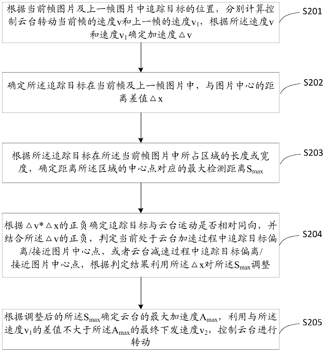
[0123] See figure 2 The steps S201 to S205 shown are specific flowcharts of a method for controlling the PTZ camera to track and perform the following steps:

[0124] Step S201: Calculate the speed v of the current frame and the speed v of the previous frame for controlling the rotation of the pan / tilt according to the position of the tracking target in the current frame picture and the previous frame picture. 1 , According to the speed v and speed v 1 Determine the acceleration △v;

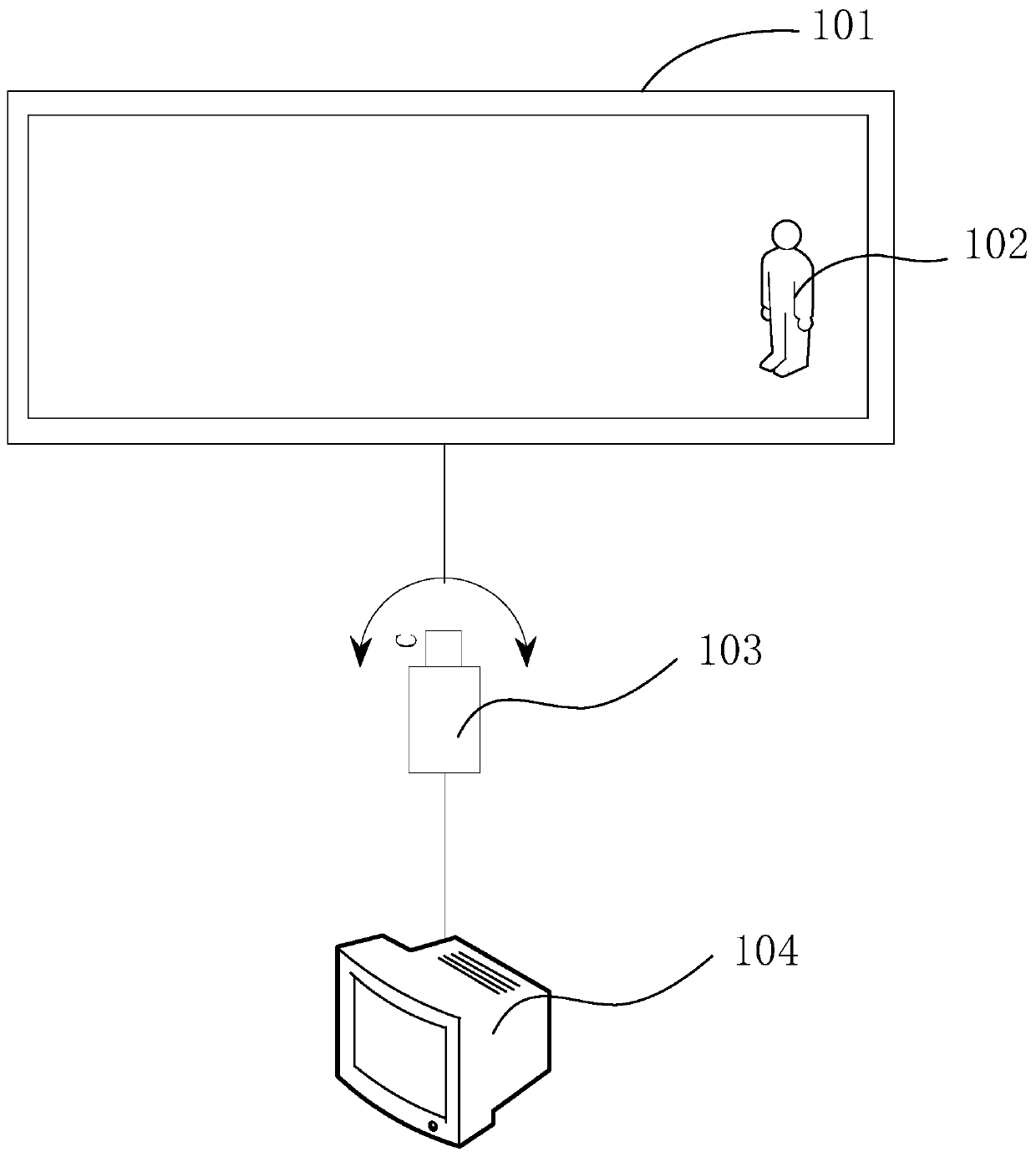
[0125] First of all, the PTZ camera will detect the current frame picture and the previous picture in the captured video. When the tracking target appears in the current frame picture and the previous frame picture, the PTZ camera will obtain the tracking target. The current frame picture and the previous frame picture.

[0126] Specifically, the target detection algorithm is used to detect whether there is a tracking target in the acquired current frame of the picture. The tracking target can be a mov...

Embodiment 2

[0167] The embodiment of the present invention calculates v and v according to the position of the tracking target in the current frame picture and the previous frame picture, and uses a motion control algorithm. 1 , The motion control algorithm will make corresponding adjustments according to the position of the tracking target relative to the picture;

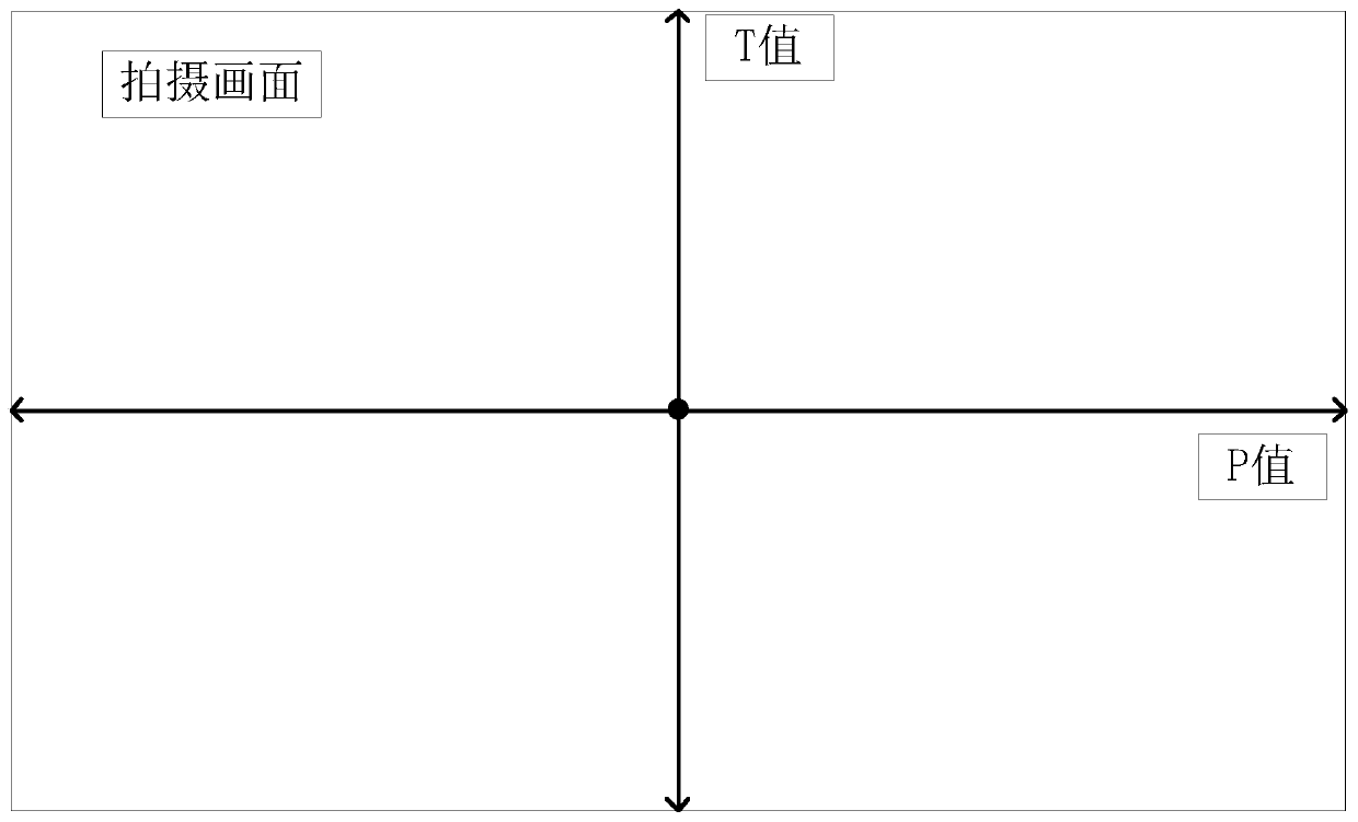
[0168] The calculation method of the motion control algorithm to calculate the speed v and v1 of the pan / tilt is specifically to set the constant coefficient K of the pan / tilt proportional term according to the parameters of the pan / tilt camera. p , The constant coefficient of the integral term is set to K i ,According to the distance e between the tracking target and the center of the frame in the i i Calculate the speed value, the i-th frame is the current frame or the previous frame, where the distance value e i They are the horizontal distance value and the vertical distance value.

[0169] As an optional implementation manner,...

Embodiment 4

[0190] In order to prevent the target from being stopped for a short period of time during the movement, and then returning to the movement state to make the gimbal rotate, excessive mechanical loss caused by repeated movement stops in a short period of time;

[0191] As an optional implementation manner, a low-speed target anti-vibration method is adopted. When a tracking target with a slower motion speed is tracked and the target is in a specific area, the motion speed of the gimbal is adjusted to 0;

[0192] According to the magnification of the lens, the area where the width and height of the current picture is reduced by a certain ratio is determined as the central area, such as Image 6 As shown, when a tracking target is detected in the central area 601, it is judged whether the pan-tilt needs to stop running.

[0193] Among them, each final issued speed v issued in embodiment 2 2 Have been stored, specifically, the historical distribution speed v 2 Stored in the issued speed a...


PUM


Abstract

The invention provides a method and device for controlling pan-tilt tracking camera shooting, and the method comprises the steps: calculating the speed v and the speed v1 of a previous frame accordingto the positions of a tracking target in a current frame of picture and the previous frame of picture, and determining the acceleration delta(v) through the speed v and the speed v1; determining a distance difference value x with the center of the picture; determining the maximum detection distance Smax of the distance tracking target; determining whether the tracking target and the pan-tilt movein the same direction or not according to the positive and negative values of delta(v)*delta(x), and adjusting the Smax by using delta(x) in combination with the positive and negative values of v; and determining the maximum acceleration Amax of the cradle head according to the adjusted Smax, and controlling the cradle head to rotate by utilizing the final issuing speed v2 of which the differencevalue with the speed v1 is not greater than the Amax. According to the invention, the problems of overshoot and oscillation generated when a traditional algorithm is used for carrying out pan-tilt tracking motion control are solved; the success rate of tracking the tracking target is improved by combining the characteristics of the detection algorithm.

Description

Technical field [0001] The present invention relates to the technical field of video surveillance, in particular to a method and device for controlling a pan-tilt to track and take pictures. Background technique [0002] At present, under the background that the society pays more and more attention to security, enterprises and the public are also paying more and more attention to the security of confidential areas, and the consequent need for tracking cameras in the security industry is also increasing. ; With the rapid development of the smart camera field, although the camera can alarm the target in the intrusion area, because the screen is at a fixed focus, the camera cannot obtain more subsequent behaviors and details of the target; therefore, in order to track the target accurately And to capture more details, the security field launched a PTZ type PTZ camera to track the target; but because the position of the target appears on the screen is uncertain, the algorithm has a d...

Claims


Application Information

Patent Timeline
IPC IPC(8): H04N5/232H04N7/18F16M11/04F16M11/12
CPCH04N7/18F16M11/04F16M11/12H04N23/695
Inventor 黄昊钱小龙陈家昱徐志文陈明珠
Owner ZHEJIANG DAHUA TECH CO LTD
Why Eureka
Try Eureka