Operation transmission mechanism of DC isolation switch

A technology of DC isolation switch and transmission mechanism, which is applied to electric switches, contact operating parts, air switch parts, etc. Good functional stability, easy to use effect

Inactive Publication Date: 2020-09-04
SUNTREE ELECTRIC CO LTD
View PDF3 Cites 2 Cited by
  • Summary
  • Abstract
  • Description
  • Claims
  • Application Information

AI Technical Summary

Problems solved by technology

[0002] The DC isolating switch is a device to prevent the AC and DC short circuits of the DC isolating switch. It is connected with an isolation transformer between the power input terminal of the AC motor power supply switch cabinet and the three-phase AC power input line, and the input of the three-phase AC power supply The wire is connected to the primary winding of the isolation transformer, and the secondary winding of the isolation transformer is connected to the power input terminal of the AC motor power supply switch cabinet. The size requirements of the product are too high, sparks are likely to be generated when the action fails or is too slow, and the device is prone to wear and tear

Method used


Image

  • Operation transmission mechanism of DC isolation switch
  • Operation transmission mechanism of DC isolation switch
  • Operation transmission mechanism of DC isolation switch

Examples


Embodiment Construction

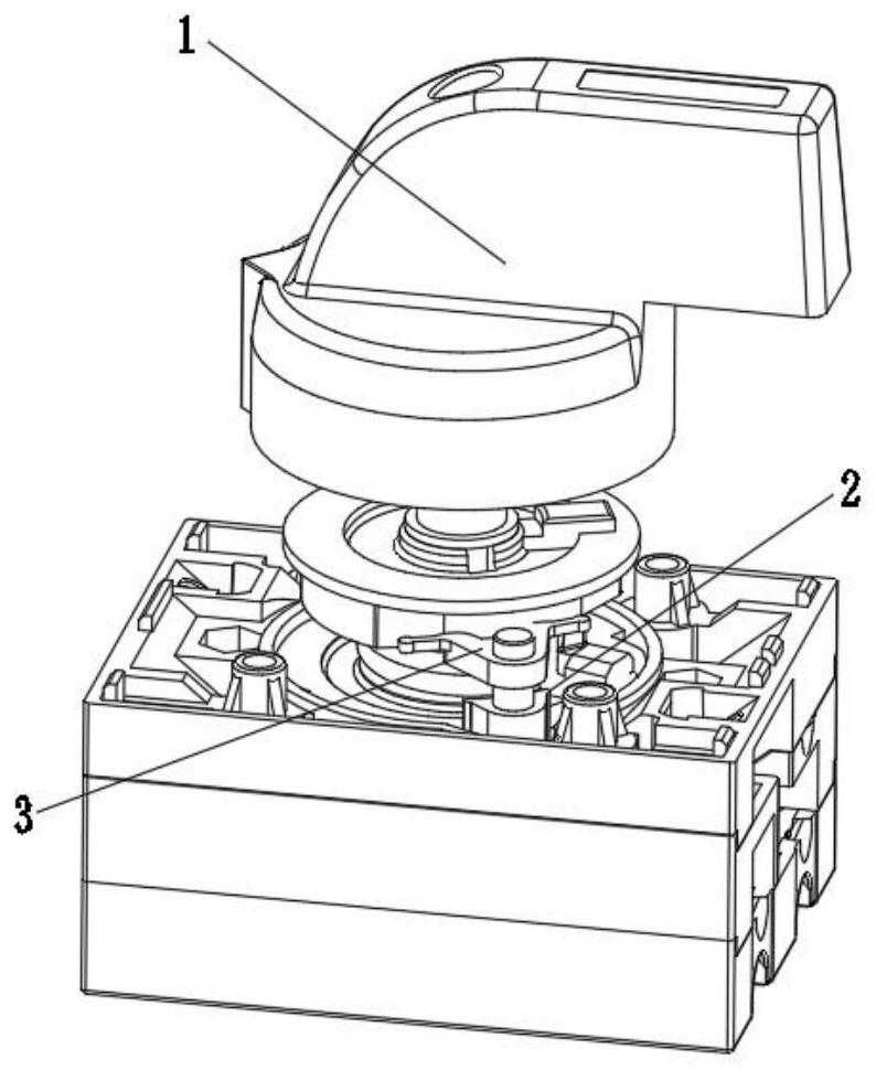
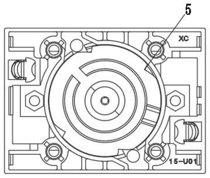
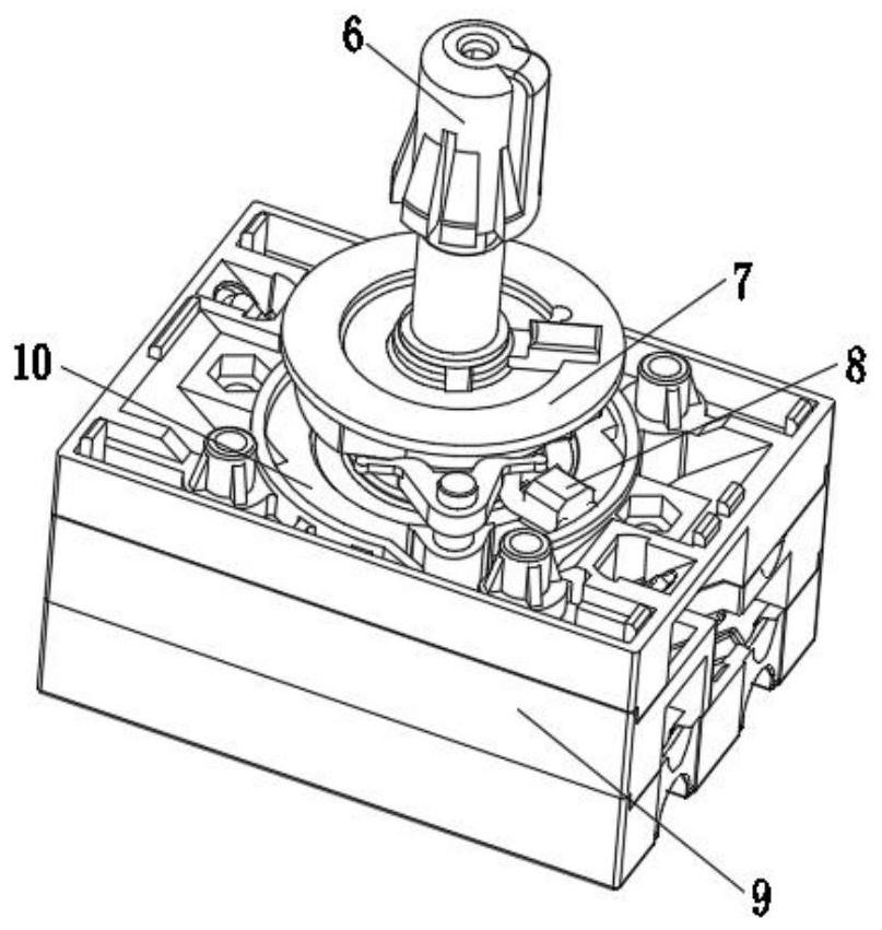
[0018] As shown in the accompanying drawings, a DC isolating switch operating transmission mechanism includes a knob cap 1 and a bottom box 9. The knob cap 1 is placed above the operating mechanism 6, and a rotating disk 7 is installed on the outside of the operating mechanism 6 below. , a top block 8 is installed under the rotating disc 7, a chassis 10 is installed under the top block 8, and a card slot 5 is opened on the chassis 10, and symmetrical stoppers are installed on both sides of the rotating disc 7. Turning block 3, block 2 is installed under the anti-rotation block 3, and connecting terminals 4 are installed on both sides of the bottom box 9;

[0019] Wherein, when the knob cap 1 is rotated, it will drive the operating mechanism 6 to rotate, and at the same time, the rotation of the rotating disk 7 will drive the top block 8 to push away the anti-rotation block 3, and the chassis 10 will rotate instantaneously until the clamping block 2 withstands the clamping groov...


PUM


Abstract

The invention discloses an operation transmission mechanism of a DC isolation switch. The operation transmission mechanism comprises a knob cap and a bottom box, the knob cap is placed above an operating mechanism; a rotating disc is arranged in the outer side of the lower portion of the operating mechanism, a top block is arranged under the rotating disc, a base plate is arranged below the top block, a clamping groove is formed in the base plate, symmetrical rotation stopping blocks are arranged at the two sides of the outer portion of the rotating disc, clamping blocks are arranged below therotation stopping blocks, and wiring terminals are arranged at the two sides of the bottom box. The operation transmission mechanism is simple and reasonable in structure and convenient to use, the clamping grooves and the clamping blocks are matched, instant opening and closing of a product can be better completed, meanwhile, the service life is longer, and the function stability is higher.

Description

technical field [0001] The invention relates to a direct current isolating switch operating transmission mechanism, which belongs to the technical field of isolating switches. Background technique [0002] The DC isolating switch is a device to prevent the AC and DC short circuits of the DC isolating switch. It is connected with an isolation transformer between the power input terminal of the AC motor power supply switch cabinet and the three-phase AC power input line, and the input of the three-phase AC power supply The wire is connected to the primary winding of the isolation transformer, and the secondary winding of the isolation transformer is connected to the power input terminal of the AC motor power supply switch cabinet. The size requirements of the product are too high, sparks are likely to be generated when the action fails and is too slow, and the device is prone to wear and tear. Contents of the invention [0003] (1) Technical problems to be solved [0004] ...

Claims


Application Information

Patent Timeline
Patent Type & Authority Applications(China)
IPC IPC(8): H01H31/02H01H3/08
CPCH01H3/08H01H31/023H01H31/026
Inventor 方杨夏初阳姜祝平李韶华
Owner SUNTREE ELECTRIC CO LTD
Why Eureka
Try Eureka