
Bundling device for straw bundling
A straw and binding line technology, which is applied in the field of binding devices for straw binding, can solve problems such as air pollution, unfavorable straw storage, and large straw bundles
Patent Information
- Authority / Receiving Office
- CN · China
- Patent Type
- Applications(China)
- Current Assignee / Owner
- Publication Date
- 2020-10-23
- Estimated Expiration
- Not applicable · inactive patent
Smart Images
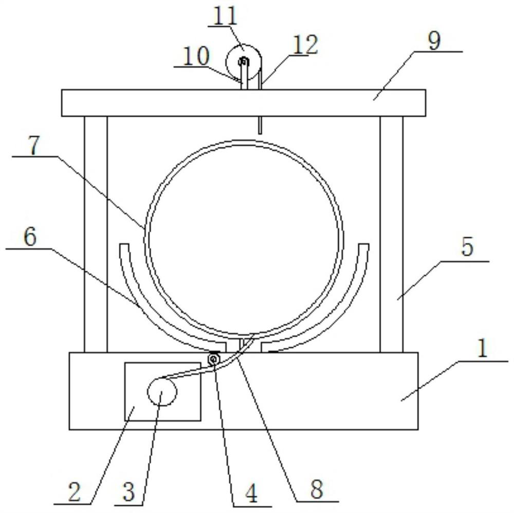
Figure 1 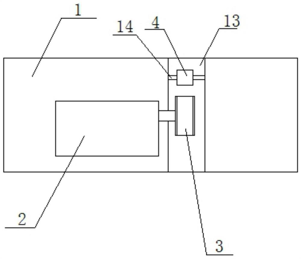
Figure 2 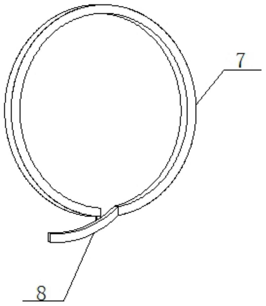
Figure 3
Abstract
Description
technical field
[0001] The invention relates to the technical field of bundling devices, in particular to a bundling device for straw bundling. Background technique
[0002] Straw is the general term for the stems and leaves (ears) of mature crops. It usually refers to the remaining part of wheat, rice, corn, potato, rapeseed, cotton, sugar cane and other crops (usually coarse grains) after harvesting the seeds. More than half of the photosynthetic products of crops exist in straw, which is rich in nitrogen, phosphorus, potassium, calcium, magnesium and organic matter, etc. It is a multi-purpose renewable biological resource, and straw is also a roughage. It is characterized by high crude fiber content (30%-40%), and contains lignin and so on. Although lignocellulose cannot be utilized by pigs and chickens, it can be absorbed and utilized by ruminant cattle, sheep and other livestock.
[0003] With the rapid development of my country's agriculture and animal husbandry, th...
Examples
Embodiment Construction
[0021] The following will clearly and completely describe the technical solutions in the embodiments of the present invention with reference to the accompanying drawings in the embodiments of the present invention. Obviously, the described embodiments are only some, not all, embodiments of the present invention. Based on the embodiments of the present invention, all other embodiments obtained by persons of ordinary skill in the art without making creative efforts belong to the protection scope of the present invention.
[0022] see Figure 1-3 , the present invention provides a technical solution: including a base 1 .
[0023] Wherein, the inside of the base 1 is provided with a winding groove 13, a winding motor 2 is fixedly installed on one side of the winding groove 13, and a winding roller 3 is fixedly connected to the output end of the winding motor 2. A limiting rod 14 is fixedly installed inside the groove 13, and a limiting roller 4 is fixedly installed on the surface...