
A method to improve filling rate
A technology of capping rate and filling slurry, which is applied in the fields of backfill, earthwork drilling, mining equipment, etc., can solve the problems of low filling and topping rate, difficult filling and topping, and difficult to observe the filling situation, so as to achieve the distribution of slurry. uniform effect
Patent Information
- Authority / Receiving Office
- CN · China
- Current Assignee / Owner
- Publication Date
- 2021-12-24
Smart Images
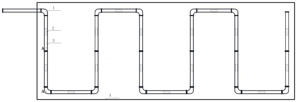
Figure 1 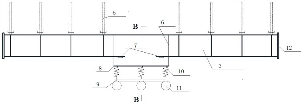
Figure 2 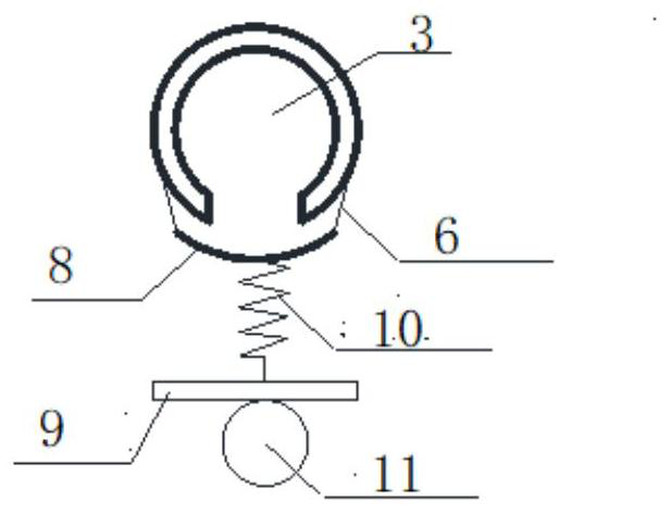
Figure 3
Abstract
Description
technical field
[0001] The invention relates to the technical field of filling and roofing, in particular to a method for improving the rate of filling and roofing. Background technique
[0002] The filling method is to mix the filling slurry with a certain cementitious material, and transport it to the underground goaf through pipelines. The filling slurry gradually hardens into a filling body to support the surrounding rock. The supporting effect of the filling body on the surrounding rock is mainly reflected in two aspects: the enclosure of the two sides and the support of the roof. When the filling slurry is filled into the goaf, it will come into close contact with the surrounding rocks of the two sides and play the role of enclosure. However, since the filling slurry is usually filled downward from the roof of the goaf, when the filling slurry level exceeds the In addition, the segregation and stratification caused by the long-distance flow will lead to uneven hydrati...
Examples
Embodiment Construction
[0026] In order to make the technical problems, technical solutions and advantages to be solved by the present invention clearer, the following will describe in detail with reference to the drawings and specific embodiments.
[0027] The invention provides a method for improving the filling rate.
[0028] The method includes steps as follows:
[0029] S1: After the filling and maintenance is completed, the roof conveying pipeline 3 is arranged along the roof in the empty area, and the middle part of the roof conveying pipeline 3 is cut to reserve a gap 2;
[0030] S2: Assemble the suspension plate 8, spring 10, floating support plate 9 and floating ball 11 to form a floating support device, and suspend the floating support device directly below the reserved gap 2 of the roof conveying pipeline 3 through the sling 6, and the distance from the reserved gap 2200mm~300mm;
[0031] S3: Arrange two miniature pressure boxes 7 symmetrically on both sides of the reserved gap 2 to ens...