Arc extinguishing chamber with multi-time arc extinguishing device

An arc-extinguishing device and arc-extinguishing hood technology are applied in the field of arc-extinguishing hoods, which can solve the problems of backflow of hot air into the contactor, poor arc-extinguishing effect, safety accidents, etc. Effects of Arc Ability

Pending Publication Date: 2022-02-18
浙江北华电气有限公司
View PDF1 Cites 0 Cited by
  • Summary
  • Abstract
  • Description
  • Claims
  • Application Information

AI Technical Summary

Problems solved by technology

Its shortcoming is that: the invention still has electric sparks and needs to be treated with flame extinguishing sheets, and the arc is guided directly into the second arc extinguishing grid through two kinds of arc extinguishing sheets, thus losing the function of primary arc extinguishing. The arc extinguishing effect is not good, and the gas production sheet is only installed on the side, which is easy to cause the gas to flow back and pour a large amount of hot air into the contactor, which may cause safety accidents

Method used


Image

  • Arc extinguishing chamber with multi-time arc extinguishing device
  • Arc extinguishing chamber with multi-time arc extinguishing device
  • Arc extinguishing chamber with multi-time arc extinguishing device

Examples


Embodiment Construction

[0032] The following will clearly and completely describe the technical solutions in the embodiments of the present invention with reference to the drawings in the embodiments of the present invention.

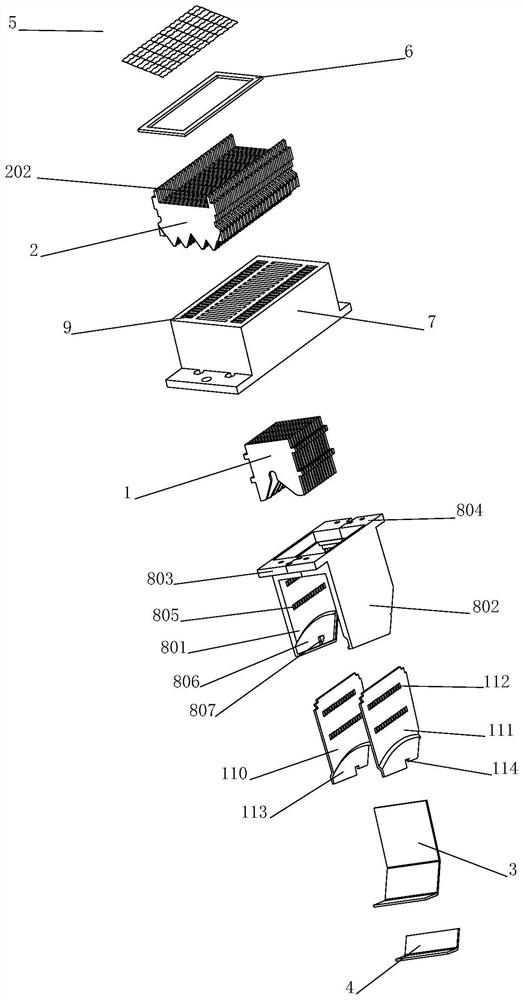
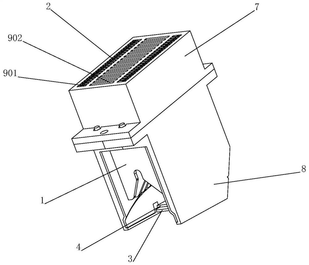
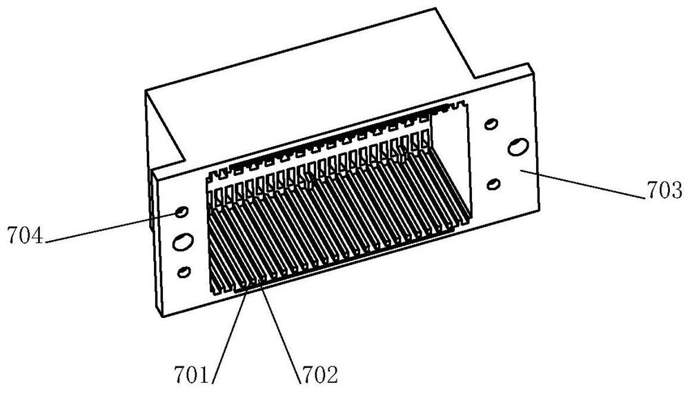
[0033] see Figure 1-8 , the present invention provides a technical solution: an arc extinguishing cover with multiple arc extinguishing devices in the present invention, including a housing, a primary arc extinguishing grid 1, a secondary arc extinguishing grid 2, an arc starting plate 3, and a gas generating plate 4. Zero flashover barbed wire 5 and insulating partition 6. The housing includes an upper housing 7 and a lower housing 8. Three rows of through-holes 9 are exposed at the upper end of the upper housing 7, and each row of twenty-five through-holes 9 serves as cooling holes for the arc extinguishing cover. Both sides of the upper end of the secondary arc extinguishing grid 2 protrude to form strips 201 and are installed in the through holes 9 on both sides, but do ...


PUM


Abstract

The invention relates to an arc extinguishing chamber with a multi-time arc extinguishing device. The arc extinguishing chamber with the multi-time arc extinguishing device comprises a shell, a first-stage arc extinguishing grid piece, a second-stage arc extinguishing grid piece, an arc striking piece, a gas production plate, a zero-flashover iron gauze and an insulating partition plate. The shell comprises an upper shell body and a lower shell body, three rows of through holes are exposed out of the upper end of the upper shell body, the two sides of the upper end of the second-stage arc extinguishing grid piece protrude to form strip prisms which are installed in the through holes, the strip prisms jointly form a groove A for containing the zero-flashover iron gauze and the insulating partition plate, and the zero-flashover iron gauze and the insulating partition plate are sequentially arranged between the through holes and the groove A from top to bottom. And the zero-flashover iron gauze covers the three rows of through holes and is in contact with the two ends of the upper side of the secondary arc chute. The upper shell and the lower shell divide the shell into an upper cavity and a lower cavity which are communicated with each other, and the lower shell is a semi-closed shell. According to the arc extinguishing chamber with the multi-time arc extinguishing device, the first-stage arc extinguishing grid piece and the second-stage arc extinguishing grid piece are arranged, and the problems of electric leakage and flashover of an existing arc extinguishing chamber are solved through multi-time arc extinguishing.

Description

technical field [0001] The invention relates to the field of arc extinguishing covers, in particular to an arc extinguishing cover with multiple arc extinguishing devices. Background technique [0002] At present, the arc extinguishing cover of the contactor is mostly composed of multiple parallel and spaced metal arc extinguishing grids and two parallel and spaced arc extinguishing grids. The stacked metal arc extinguishing grids are fixed in a roughly parallel state. An escape groove is provided in the center of the metal arc extinguishing grid, so that when a plurality of metal arc extinguishing grids are stacked, a cavity for accommodating the movement of the moving contact is formed in the center of the stacked metal arc extinguishing grid. When the moving and static contacts are separated, the arc generated enters the arc extinguishing grid under the action of electromotive force, and will be divided into multiple short arcs in series by the metal arc extinguishing gr...

Claims


Application Information

Patent Timeline
Patent Type & Authority Applications(China)
IPC IPC(8): H01H9/30H01H50/00
CPCH01H9/30H01H50/00
Inventor 王海祥黄朝波郑豪豪倪贤济
Owner 浙江北华电气有限公司
Why Eureka
Try Eureka