

Redundant touch switch using induction proximity sensors
a proximity sensor and redundancy technology, applied in electronic switching, electrical equipment, pulse techniques, etc., can solve problems such as restricted operability and exterior appearance, and achieve the effect of increasing design flexibility and improving operability of the keyboard
- Summary
- Abstract
- Description
- Claims
- Application Information
AI Technical Summary
Benefits of technology
Problems solved by technology
Method used
Image


Examples
first embodiment
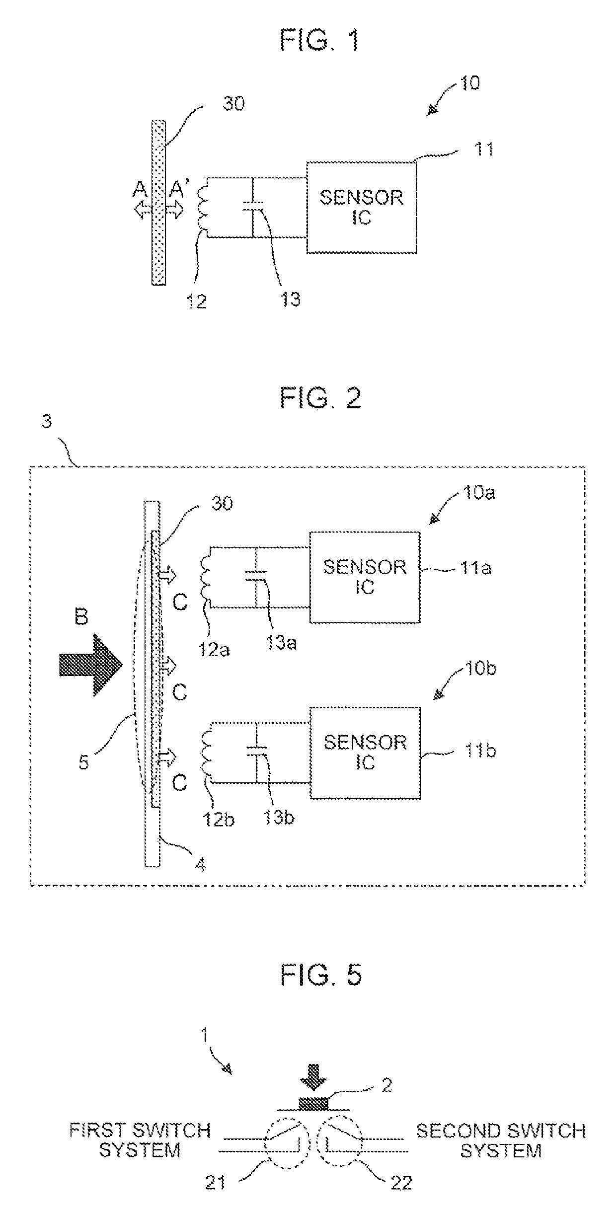
[0023]A duplicated touch switch according to the present invention will next be described with reference to FIG. 2.
[0024]A duplicated touch switch 3 according to the present embodiment includes a touch input section 5, which is formed of the metal piece 30 bonded to part of an operation board enclosure 4, and at least two induction-type proximity sensors 10a, 10b, . . . , which are located in the vicinity of the enclosure interior side of the touch input section 5, as shown in FIG. 2.
[0025]The touch input section 5 is formed by fitting the metal piece 30 to, burying the metal piece 30 in, or attaching the metal piece 30 to, cover of the operation board enclosure 4. The cover that is part of the operation board enclosure 4 and forms the touch input section 5 is made of a resin or any other elastic material and is therefore elastically deformed by a small amount in the direction indicated by the arrow C in FIG. 2 when the bonded metal piece 30 receives pressure produced by contact of ...
second embodiment
[0027]A duplicated touch switch according to the present invention will next be described with reference to FIG. 3.
[0028]In a duplicated touch switch 3 according to the present embodiment, the induction-type proximity sensor 10a is disposed in the vicinity of the enclosure interior side of the touch input section 5 including a metal piece 30a, and an auxiliary sensing section 7 is disposed on the enclosure interior side of the induction-type proximity sensor 10a, as shown in FIG. 3. The auxiliary sensing section 7 is then linked with the touch input section 5 via a linkage section 6, and the induction-type proximity sensor 10b is disposed in the vicinity of on the enclosure interior side of the auxiliary sensing section 7. The auxiliary sensing section 7 includes a metal piece 30b, as the touch input section 5 does. The linkage section 6 is made of a material rigid enough to withstand against external pressure, and when the touch input section 5 is displaced in the direction indicat...
third embodiment
[0034]A duplicated touch switch according to the present invention will next be described with reference to FIG. 4.
[0035]In a duplicated touch switch 3 according to the present embodiment, the auxiliary sensing section 7 is disposed on the enclosure interior side of the touch input section 5, the auxiliary sensing section 7 is linked with the touch input section 5 via the linkage section 6, and the induction-type proximity sensors 10a and 10b are disposed in the vicinity of the enclosure exterior side and in the vicinity of the enclosure interior side of the auxiliary sensing section 7, respectively, as shown in FIG. 4. The auxiliary sensing section 7 includes the metal piece 30. The linkage section 6 is made of a material rigid enough to withstand against external pressure, and when the touch input section 5 is displaced in the direction indicated by the arrow H in FIG. 4, the displacement is transmitted to the auxiliary sensing section 7 via the linkage section 6.
[0036]The LC osci...
PUM
 Abstract
Description
Claims
Application Information