Image forming apparatus having recording medium positioning portion and control of transport speed

a technology of image forming apparatus and positioning portion, which is applied in the direction of electrographic process apparatus, instruments, optics, etc., to achieve the effect of reducing speed difference and reducing time variation

Active Publication Date: 2020-11-10
FUJIFILM BUSINESS INNOVATION CORP
View PDF17 Cites 0 Cited by
  • Summary
  • Abstract
  • Description
  • Claims
  • Application Information

AI Technical Summary

Benefits of technology

[0004]Aspects of non-limiting embodiments of the present disclosure relate to obtaining an image forming apparatus capable of increasing the precision of the timing at which a medium is transported to a transfer portion as compared with a configuration in which the change point of the transport speed is provided at only one position in a period from when transport of the medium is started to when the medium is transported to the transfer portion.
[0006]According to an aspect of the present disclosure, there is provided an image forming apparatus including a positioning portion that is provided upstream of a transfer portion in a transport direction of a medium which is an image formation object, and that positions the medium by bringing a leading end of the medium into contact with the positioning portion; a driving source that provides a driving force to transport the medium positioned at the positioning portion; a detector that is disposed downstream of the positioning portion in the transport direction, and that detects passage of the leading end of the medium; and a controller that controls a transport speed in a period from when the leading end of the medium passes through the detector to when the leading end of the medium passes through a target position situated downstream of the detector in the transport direction, in accordance with a time since transport of the medium is started from the positioning portion until the leading end of the medium passes through the detector, so as to decrease a variation in the time since the transport of the medium is started by the driving source until the leading end of the medium passes through the target position and so as to decrease a speed difference between the transport speed of the medium and a driving speed in the transfer portion in a period from when the leading end of the medium passes through the target position until when the leading end of the medium enters the transfer portion.

Problems solved by technology

However, aspects of the non-limiting embodiments are not required to address the advantages described above, and aspects of the non-limiting embodiments of the present disclosure may not address advantages described above.

Method used


Image

  • Image forming apparatus having recording medium positioning portion and control of transport speed
  • Image forming apparatus having recording medium positioning portion and control of transport speed
  • Image forming apparatus having recording medium positioning portion and control of transport speed

Examples


first exemplary embodiment

[0016]The apparatus 10 according to the first exemplary embodiment is now described with reference to FIGS. 1 to 5.

General Configuration of Image Forming Apparatus 10

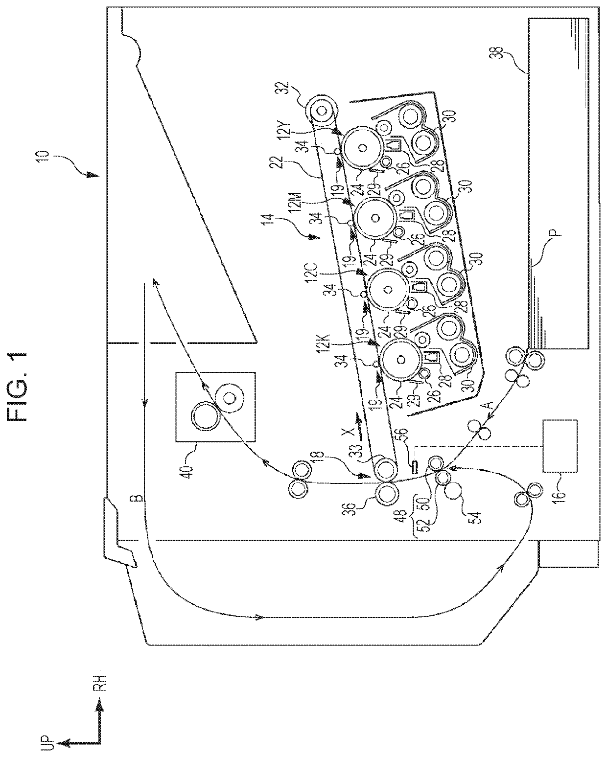
[0017]A configuration of the image forming apparatus 10 is now described. FIG. 1 is a front view schematically illustrating the image forming apparatus 10 according to this exemplary embodiment.

[0018]As illustrated in FIG. 1, the image forming apparatus 10 includes an image forming unit 12 that forms an image by electrophotographic system, an intermediate transfer belt 22 that holds the formed image, and an intermediate transfer unit 14 that holds the intermediate transfer belt 22. In addition, a second transfer roller 36 that transfers the image from the intermediate transfer unit 14 to a sheet P for image recording (corresponding to an example of a medium of an image formation object) is provided on the left side of the intermediate transfer unit 14.

[0019]A contact portion of the intermediate transfer belt 22 and the ...

second exemplary embodiment

[0065]An apparatus 10 according to a second exemplary embodiment is now described with reference to FIGS. 1, 2, 6, and 7. The second exemplary embodiment is a modification of the first exemplary embodiment, and hence like reference signs are applied to like configurations and the description thereof is omitted.

Driving Source 54

[0066]In this exemplary embodiment, the driving source 54 illustrated in FIG. 1 is a direct-current (DC) motor. When the driving source 54 uses a stepping motor, the size and the current value for driving may increase, for example, in order to avoid loss of synchronism. Thus, as compared with the configuration employing the DC motor, the manufacturing cost and running cost may increase. In contrast, when the DC motor is employed, the size and cost may be decreased.

[0067]However, with the DC motor, a transient response may not occasionally follow an input as compared with the case employing the stepping motor.
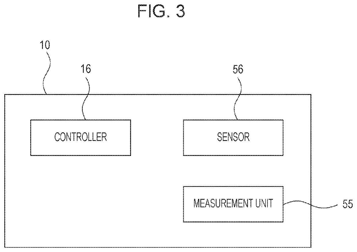
Measurement Unit 55

[0068]In this exemplary embodimen...


PUM


Abstract

Provided is an image forming apparatus including a positioning portion provided upstream of a transfer portion in a transport direction of a recording medium. The positioning portion positions the medium using a leading end of the medium. Additionally included is a detector that is disposed downstream of the positioning portion in the transport direction, and that detects passage of the leading end of the medium; and a controller that controls a transport speed in a period from when the leading end of the medium passes through the detector to when the leading end of the medium passes through a target position situated downstream of the detector in the transport direction, in accordance with a time since transport of the medium is started from the positioning portion until the leading end of the medium passes through the detector.

Description

CROSS-REFERENCE TO RELATED APPLICATIONS[0001]This application is based on and claims priority under 35 USC 119 from Japanese Patent Application No. 2019-048801 filed Mar. 15, 2019.BACKGROUND(i) Technical Field[0002]The present disclosure relates to an image forming apparatus.(ii) Related Art[0003]Japanese Patent Application Publication No. 2008-133111 discloses a sheet transport apparatus including a transport unit that transports a sheet and a controller that controls the transport speed of the transport unit. A speed-change control point is provided in the middle of a sheet transport path. The controller sets the transport speed of the transport unit to a first setting speed on the upstream side of the speed-change control point; obtains correlation between the first setting speed and the actual transport speed; and changes the speed of the transport unit after the sheet passes through the speed-change control point to a second setting speed based on the correlation.SUMMARY[0004]A...

Claims


Application Information

Patent Timeline
Patent Type & Authority Patents(United States)
IPC IPC(8): G03G15/00
CPCG03G15/6594G03G15/6564G03G2215/00409G03G2215/00599G03G15/6529G03G15/50Y02P70/10
Inventor IIJIMA, CHIHIROTOKAIRIN, MOTOHIRO
Owner FUJIFILM BUSINESS INNOVATION CORP
Why Eureka
Try Eureka