Putter striking face configuration to progressively reduce dispersion

a technology of striking face and putter, which is applied in the field of golf clubs, can solve problems such as cumbersome shapes and unattractive to the eye of golfers

Active Publication Date: 2022-08-23
EVNROLL PUTTERS LLC
View PDF91 Cites 2 Cited by
  • Summary
  • Abstract
  • Description
  • Claims
  • Application Information

AI Technical Summary

Benefits of technology

The present invention provides a golf putter with a flat, rigid surface that has V-shaped channels on its face. These channels form a gripping edge that creates a directional gripping action against the golf ball when it is hit. The shape of the channels is designed to match the impact from off-center hits, allowing the putter to direct the ball towards the intended target line and increasing accuracy. The putter also has closely spaced parabolic or arcuate channels that create a progressive inward gearing effect, counteracting the outward dispersion caused by miss hits. The width of the channels tapers outwardly towards the heel and toe of the putter face, creating a wider inward face shape and a greater gearing effect. This technology eliminates the effect of miss hits and allows golfers to make more putts and hit the ball better.

Problems solved by technology

While these putter head designs help golfers to be more accurate, they tend to be very large and often, with cumbersome shapes that may be unattractive to the eye of the golfer.
Whereas the above described putters provide some improvement in the way a golf ball rolls, the resulting putts still usually miss the intended target thereby leaving room for improved performance.

Method used


Image

  • Putter striking face configuration to progressively reduce dispersion
  • Putter striking face configuration to progressively reduce dispersion
  • Putter striking face configuration to progressively reduce dispersion

Examples


Embodiment Construction

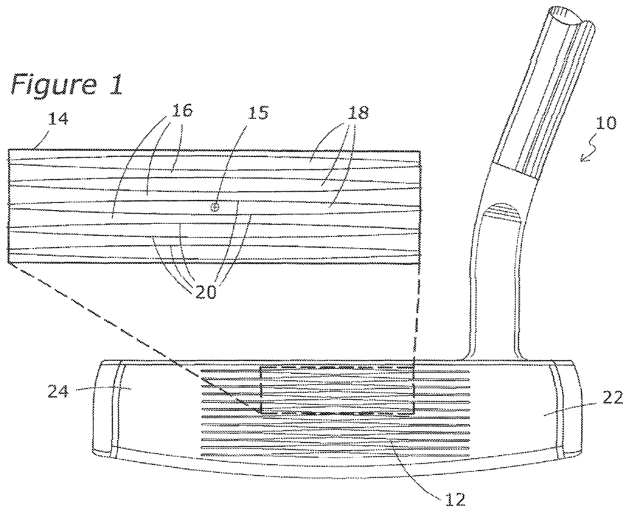
[0030]FIG. 1 illustrates a conventional type golf putter 10 having a ball striking face 12 that contacts the golf ball during a putting stroke. A hitting area 14 where a golf ball is normally struck during the execution of a putting stroke is shown as an exploded, enlarged detail of the face 14. This hitting area 14 is structured to progressively direct a golf ball to roll in a straight direction when hit away from the midpoint 15 of the hitting area 14 and not angle away from the target line as described in detail in this application.

[0031]A series of ball contact, land areas 16 are an integral part of the hitting area 14 of the face 12 and are the only part of the face 12 that actually contacts the golf ball during the putting stroke. Individual ball contact, land areas 16 are separated by a series of recessed channels 18 in the face 12 that do not contact the golf ball during the putting stroke. The ball contact areas land areas 16 and the recessed channels 18 extend longitudinal...


PUM


Abstract

A putter type golf club head having a frontal ball striking face that engages and grips a golf ball during the execution of a putting stroke to direct the golf ball in a straight line toward the intended target. The face includes a plurality of ball striking land areas and a plurality of adjacent and complimentary recessed channels that form an opening toward and on either side of the midpoint of the hitting area of the face. The ball contact areas are smaller than the adjacent recessed channels at the midpoint of the hitting area of the face. Gripping edges at the interface of the land areas and the recessed channels redirect the golf ball toward the intended target when the ball is miss hit away from the midpoint of the face.

Description

FIELD OF THE INVENTION[0001]The present invention relates to golf clubs and in particular to a configuration of the striking face of a putter.BACKGROUND OF THE INVENTION[0002]The game of golf is played with 14 clubs. One of those clubs, the putter, is responsible for approximately 40% of the total score of a round of golf. It is therefore very important to be accurate when using a putter to roll a golf ball toward and into the golf hole.[0003]The putter is different from the rest of the other clubs in a set of golf clubs. All of the other clubs have varying degrees of loft in order to strike a golf ball with enough velocity to create a desired degree of upward launch and distance to propel a golf ball toward a target such as a fairway or putting green area that contains a hole. Once on the green the golfer must then roll the ball to the hole as accurately as possible. To do this it requires a club that has only 1 to four degrees of loft so that when struck typically with a putter he...

Claims


Application Information

Patent Timeline
Patent Type & Authority Patents(United States)
IPC IPC(8): A63B53/04
CPCA63B53/0487A63B53/0445
Inventor RIFE, GUERIN D.
Owner EVNROLL PUTTERS LLC
Why Eureka
Try Eureka