Card connector

a card connector and connector technology, applied in the direction of coupling devices, two-part coupling devices, electrical equipment, etc., can solve the problems of difficult to distinguish the front and back sides of cards, and the problem becomes worse, so as to prevent wrong insertion of cards

Inactive Publication Date: 2007-08-30
HIROSE ELECTRIC GROUP
View PDF8 Cites 7 Cited by
  • Summary
  • Abstract
  • Description
  • Claims
  • Application Information

AI Technical Summary

Benefits of technology

[0008]Accordingly, it is an object of the invention to provide a card connector having high withstanding power against wrong card insertion.
[0011]The card may have an inclined face between a front narrow section and a rear wide section of the card. The card connector further comprises an ejector that is able to slide in the housing in the card nsertion / removal direction and normally biased toward the card insertion opening. The ejector may have an inclined face that corresponds to the inclined face of the card so that when the card is inserted correctly, it is inserted into the housing with the inclined face of the card fitting with the inclined face of the ejector while if the card is inserted upside down, the inclined face of the ejector abuts against another face of the card, making the card inclined and preventing wrong insertion of the card.

Problems solved by technology

When the connector or card is miniaturized, it is difficult to distinguish the front and back sides of a card.
Especially, when a compact card is inserted into a mobile device, such as a cell phone, this problem becomes worse because the mobile device itself can turn upside down.

Method used


Image

  • Card connector
  • Card connector
  • Card connector

Examples


third embodiment

[0035]In FIG. 8, a first protective member 70B is provided with a bent portion 78 to cover at least a portion of the housing where a card is inserted in the direction of arrow C. An extended section 79 extends from the top face 42 of the cover 30 and has an engaging hole 81 for receiving an engaging projection 80 of the bent section 78 so as to reinforce the bent section 78.

fourth embodiment

[0036]In FIG. 9, a first protective member 70C has a bent section 82 to cover at least a portion of the housing. In order to reinforce the bent section 82, the first protective member 70C has a fixing section 74C that is soldered to the board 37 together with the soldering section 35 of the cover 30. In this way, by providing the fixing section or engaging section, it is possible to reinforce the member that receives a force from pushing of the inclined card.

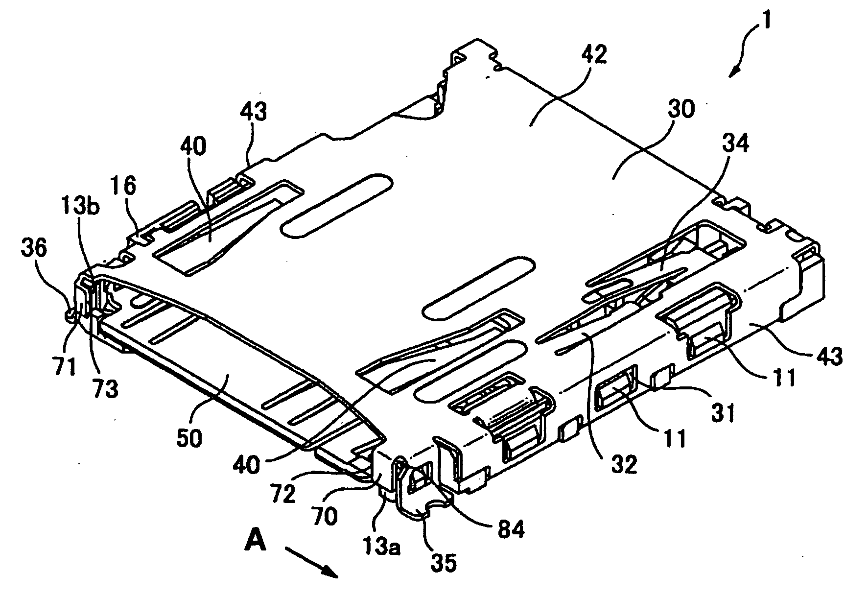
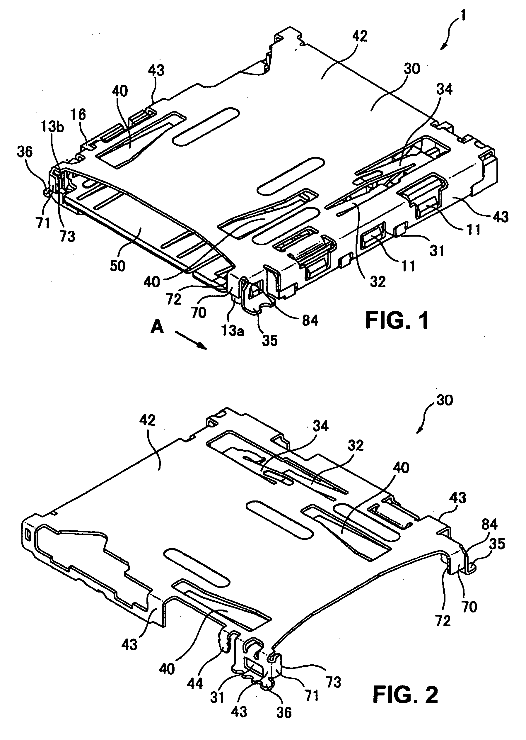
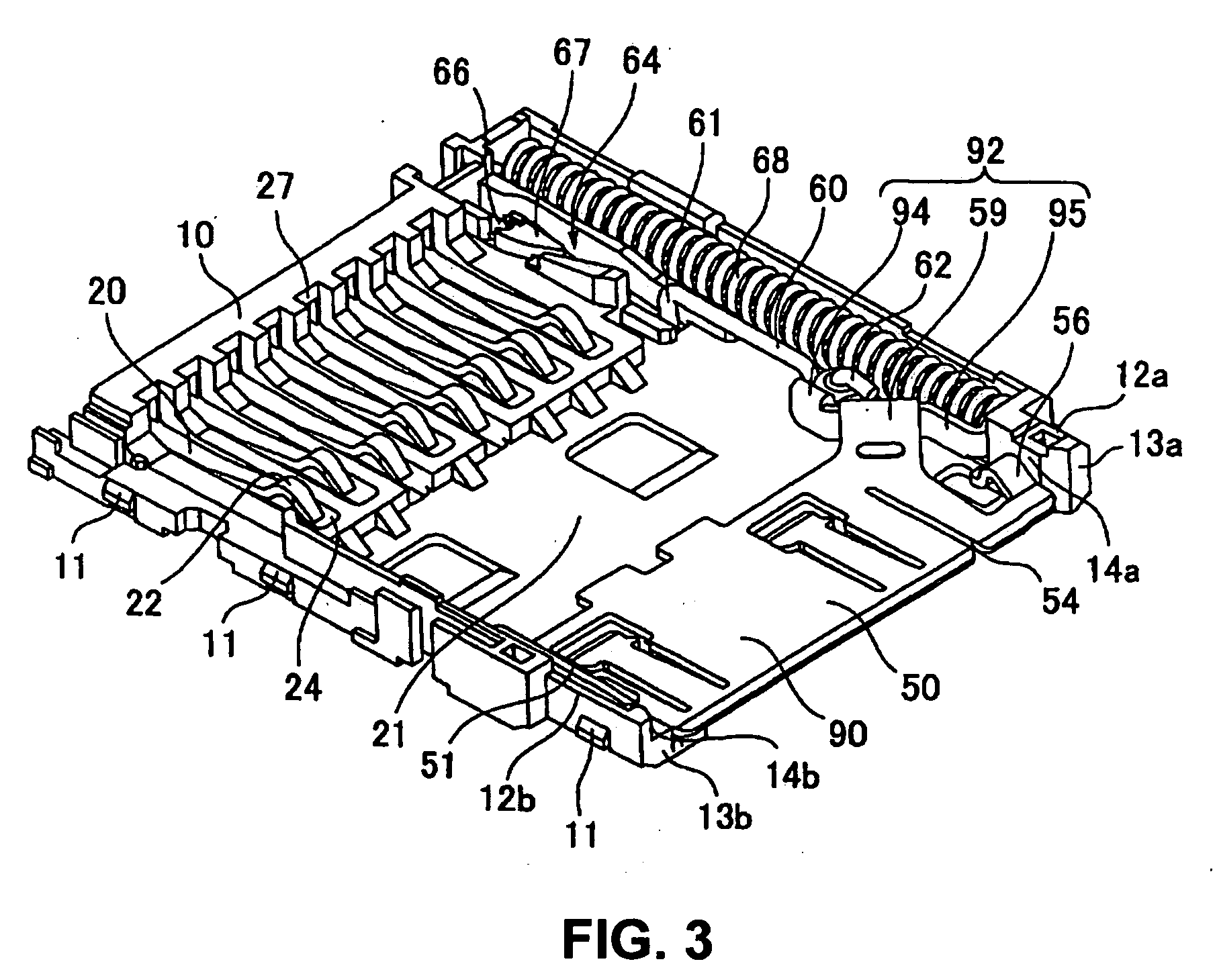
[0037]Referring back to FIG. 5, when the card 3 is inserted upside down, the front end of the card 3 abuts against the lock spring 56 of the ejector, and the side face 88 of the card 3 abuts against the spring abutment 58 or inclined card abutment 59 so that the card 3 is made inclined. At this point, the side section 72 of the first protective member 70 abuts against the side face 88 of the card 3 while the side section 73 of the second protective member 71 buts against the side face 87, especially, the inclined face 89 of the...


PUM


Abstract

A card connector (1) includes a housing (10) having a card insertion opening at its front end into which a card (3) is inserted in a card insertion / removal direction and a metallic cover (30) for covering top and side faces of the housing (10). The housing has a pair of side walls (12a, 12b) extending in the card insertion / removal direction. The cover (30) has a protective member (70, 71) at the card insertion opening for protecting at least a portion of a front end of at least one of the side walls (12a, 12b).

Description

BACKGROUND OF THE INVENTION[0001]1. Field of the Invention[0002]The present invention relates to card connectors and, particularly, to a card connector with a protection against wrong card insertion.[0003]2. Description of the Related Art[0004]FIG. 10 shows a conventional card connector. This card connector 9 is disclosed in JP 2003-109694 and includes a housing 7, a plurality of terminals 5 arranged on the housing 7, and a metal cover 8 that covers the top and side faces of the housing 7 except for the card insertion side 15.[0005]Where a card (not shown) is inserted into the connector 9 in a wrong direction, for instance, upside down, the card is inserted along the side walls 4a and 4b to a certain extent and then blocked from further insertion. If the card is pushed further into the inside, the contact or slider of the connector can be broken.[0006]When the connector or card is miniaturized, it is difficult to distinguish the front and back sides of a card. Especially, when a com...

Claims


Application Information

Patent Timeline
Patent Type & Authority Applications(United States)
IPC IPC(8): H01R24/00
CPCH01R13/635H01R12/72
Inventor NISHIWAKI, KENJIMIYAMOTO, OSAMU
Owner HIROSE ELECTRIC GROUP
Why Eureka
Try Eureka