Ball glove with finger stalls having multiple weltings

a glove and finger stall technology, applied in the field of ball glove, can solve the problems of many existing ball glove drawbacks, finger stalls of many ball glove stalls can become too flexible, and the tendency to bend backwards

a glove and finger stall technology, applied in the field of ball glove, can solve the problems of many existing ball glove drawbacks, finger stalls of many ball glove stalls can become too flexible, and the tendency to bend backwards

US20080216202A1Inactive Publication Date: 2008-09-11WILSON SPORTING GOODS

Image

  • Ball glove with finger stalls having multiple weltings
  • Ball glove with finger stalls having multiple weltings
  • Ball glove with finger stalls having multiple weltings

Examples


Embodiment Construction

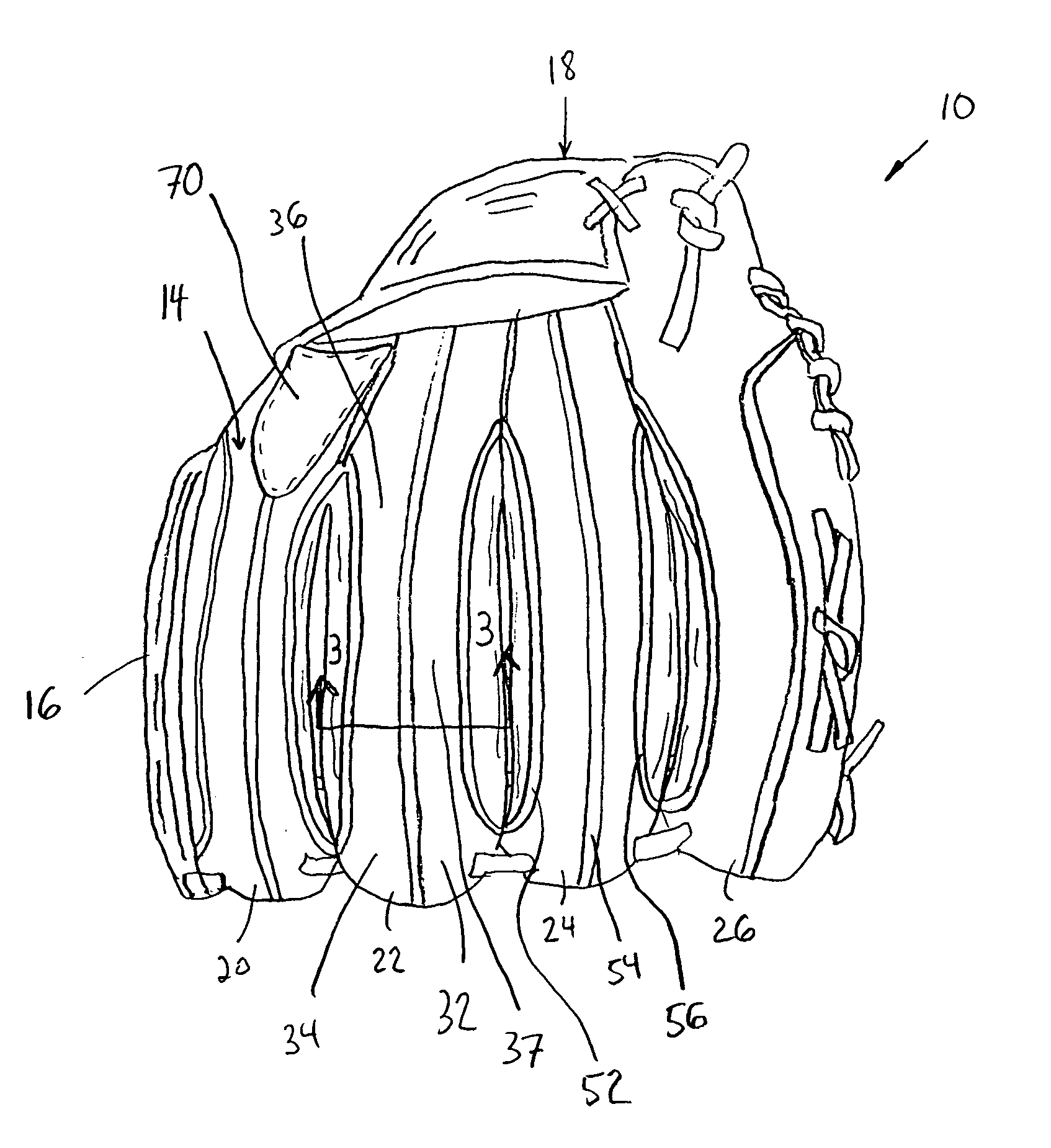
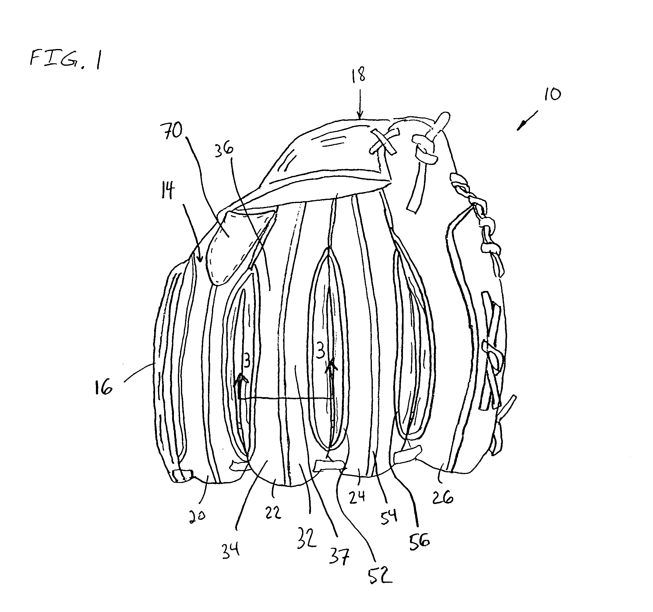
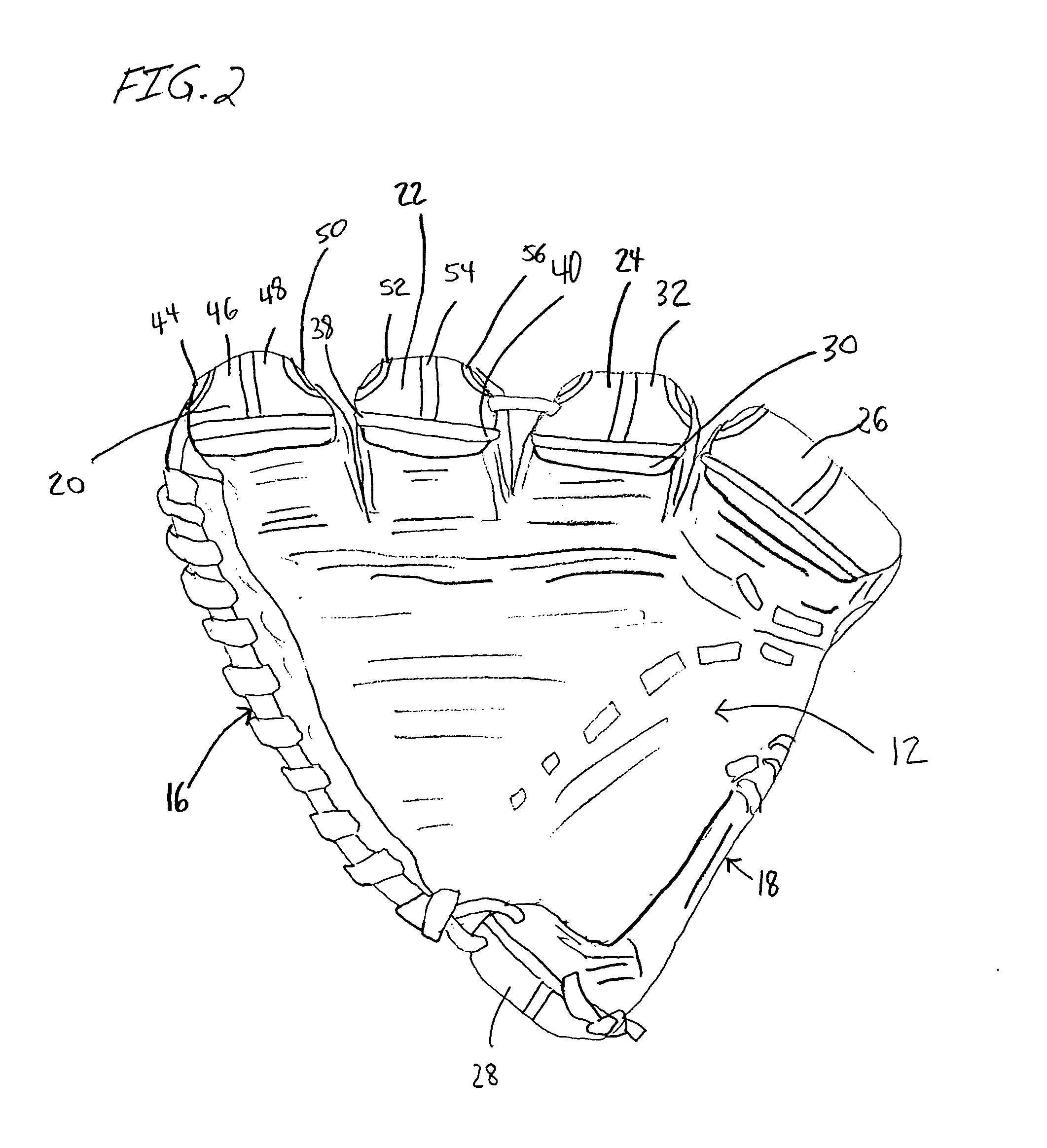
[0013]Referring to FIGS. 1 and 2, a ball glove is indicated generally at 10. The ball glove 10 is configured for use in baseball, softball, hockey and other sports involving ball gloves. The ball glove 10 can also be referred to as a mitt. The present invention is directly applicable to any ball glove or ball mitt including, for example, a first baseman mitt and a catcher's mitt. The ball glove 10 includes a front glove portion 12, a back glove portion 14 and a webbing 16. The front and back portions 12 and 14 are contoured sheet-like structures, each resembling a hand. The front and back portions 12 and 14 are connected together to define a hand cavity 18, and to form first, second, third and fourth finger stalls 20, 22, 24, 26, and a thumb stall 28. The front and back portions 12 and 14 are preferably stitched together. In one preferred embodiment, the front and back portions 12 and 14 are coupled together through the use of weltings. Alternatively, the front and back portions 12 ...


PUM


Abstract

A ball glove including front and back glove portions, at least first and second weltings, and a webbing. The back glove portion is coupled to the front glove portion to define a hand cavity and to form first, second, third and fourth finger stalls and a thumb stall. Each finger stall includes a front stall portion and a back stall portion. Each back stall portion includes at least three stall segments. The first and second weltings extending along the back stall portion and each welting connects two of the stall segments. The webbing is coupled to, and positioned between, the first finger stall and the thumb stall.

Description

FIELD OF THE INVENTION[0001]The present invention relates generally to a ball glove for baseball, softball and other sports. In particular, the present invention relates to a ball glove having a plurality of finger stalls with at least two weltings reinforcing the back portion of at least one of the finger stalls.BACKGROUND OF THE INVENTION[0002]Ball gloves for use in baseball, softball and other sports are well known. Ball gloves typically include a front panel connected to a corresponding back panel to form a hand cavity. The front and back panels typically generally resemble the shape of a human hand and when assembled form five stalls for receiving the thumb and fingers of a user's hand. The front and back panels form a hand opening at the lower edge of the glove. A webbing is typically connected between the thumb stall and the index finger stall of the ball glove. Ball gloves also typically include a hand opening for enabling a user to insert his or her hand into the hand cavit...

Claims


Application Information

Patent Timeline
11 Sep 2008
Publication
US20080216202A1
IPC
A63B71/14
CPC
A63B71/143
Inventors
LIN, HSIN FENG; ASO, SHIGEAKI