Lock mechanism for seat track slide device

Active Publication Date: 2012-05-31
TOYOTA BODY SEIKO CO LTD
View PDF6 Cites 33 Cited by
  • Summary
  • Abstract
  • Description
  • Claims
  • Application Information

AI Technical Summary

Benefits of technology

[0005]Accordingly, it is an objective of the present invention to provide a lock mechanism for a seat track slide device that has an enlarged relative pivoting range of a lock member and a handle in an interlock support portion, which is arranged between the lock member and the handle, and improves the unlocking prevention function of the lock member.

Problems solved by technology

This easily causes contact between the handle and the upper rails when the handle pivots relative to the lock levers, thus limiting the range in each upper rail that allows the handle and the associated lock lever to pivot relative to each other.

Method used


Image

  • Lock mechanism for seat track slide device
  • Lock mechanism for seat track slide device
  • Lock mechanism for seat track slide device

Examples


Embodiment Construction

[0021]A lock mechanism for a seat track slide device according to one embodiment of the present invention will now be described with the attached drawings.

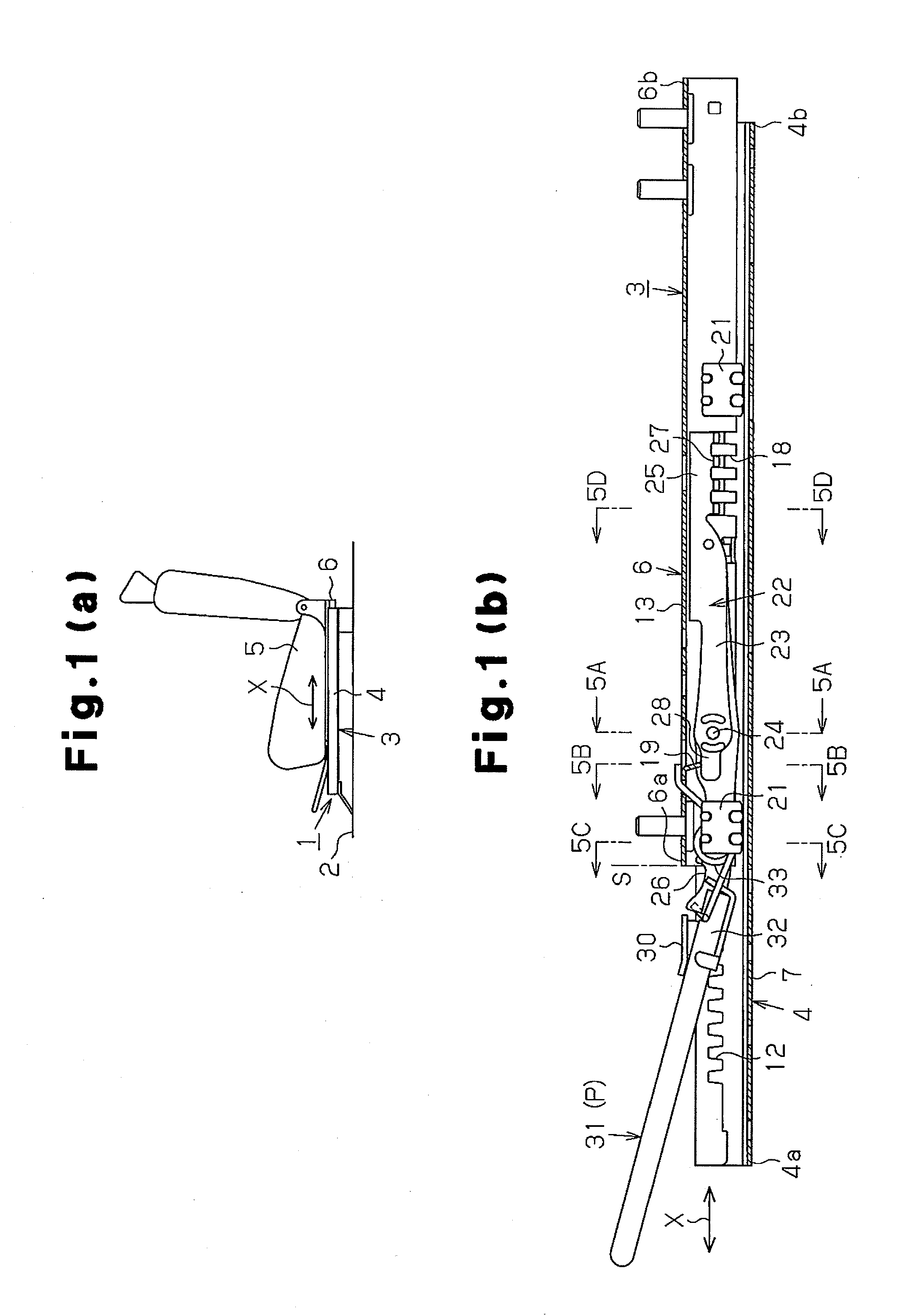
[0022]As schematically shown in FIG. 1(a), a seat track slide device 1 is attached to a floor 2 of a vehicle and has a pair of seat tracks 3, which extend in the fore-and-aft directions X. The two seat tracks 3 are spaced from each other in the direction perpendicular to the fore-and-aft directions X, or, in other words, the widthwise direction of the vehicle. The seat tracks 3 are arranged in correspondence with both sides of a seat 5. Each of the seat tracks 3 includes a lower rail 4 and an upper rail 6. The lower rails 4 are fixed to the floor 2. Each of the upper rails 6, which is fixed to the corresponding one of the two sides of the seat 5, is inserted into the corresponding one of the lower rails 4 and supported to be movable in the fore-and-aft directions X.

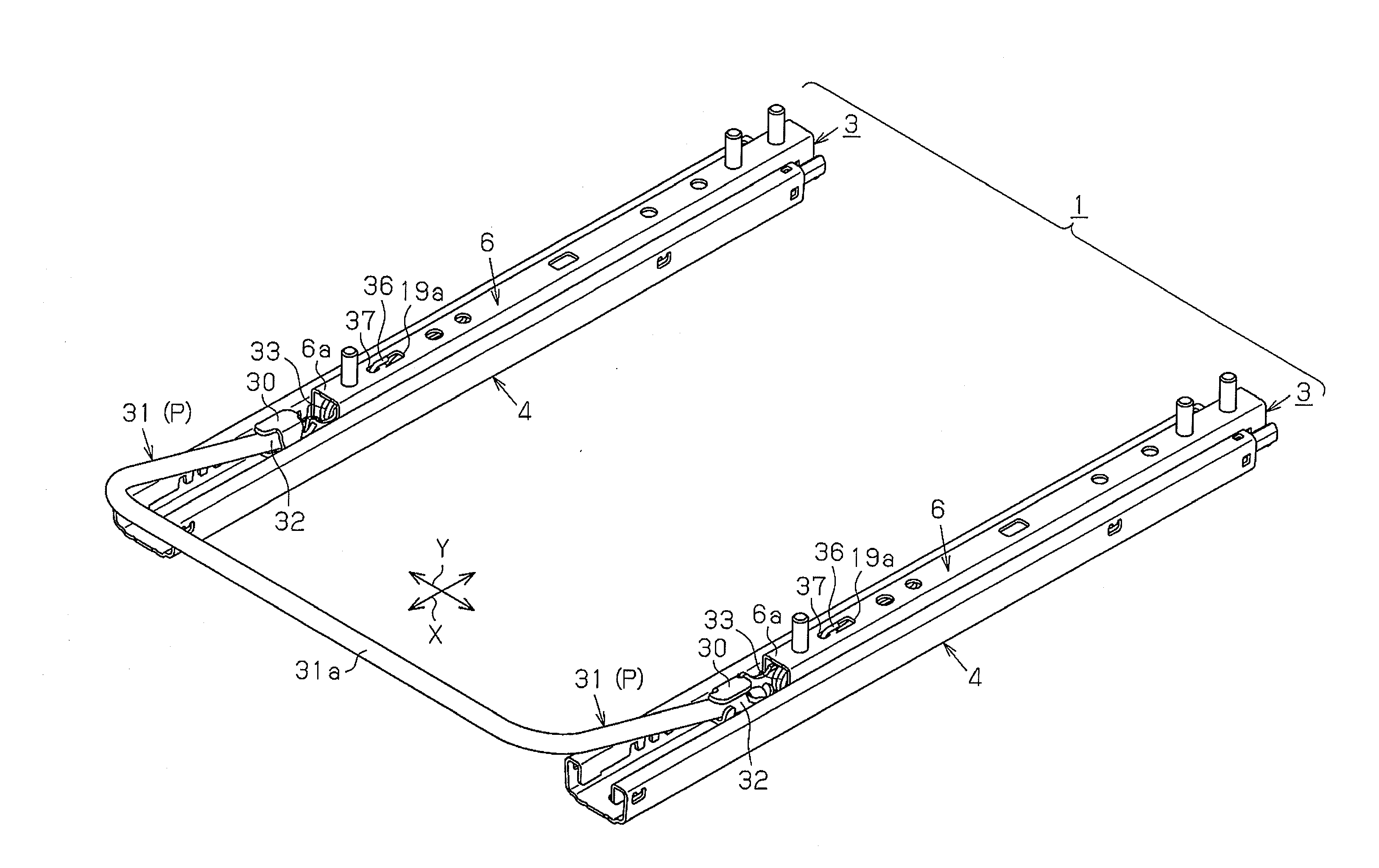
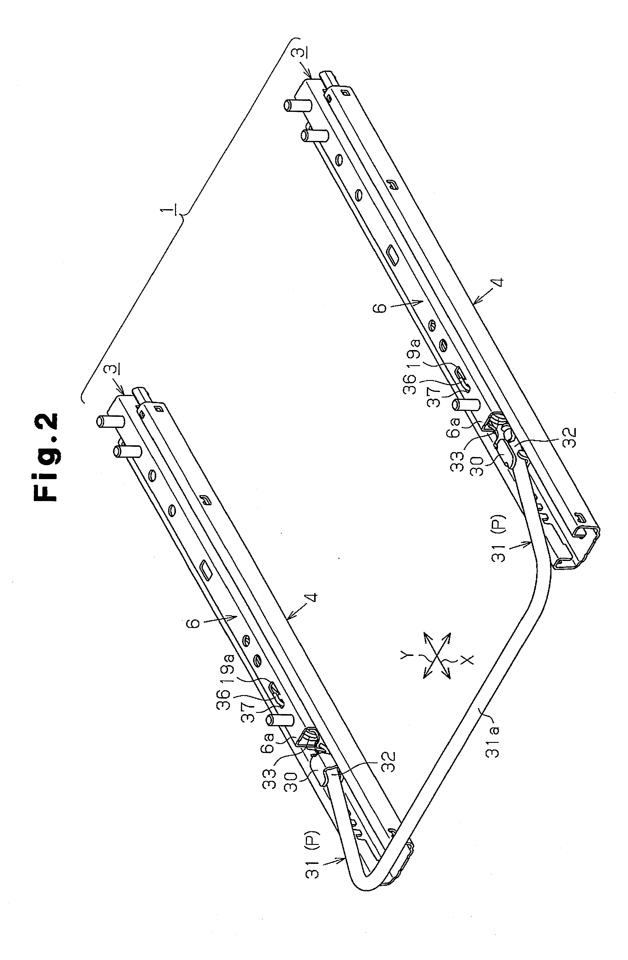
[0023]FIG. 2 shows the seat track slide device 1 as a whole. With ...


PUM


Abstract

A seat track slide device includes a pair of seat tracks. Each of the seat tracks has a lower rail, an upper rail, a lock lever, and a handle. Through manipulation of the handle, each seat track 3 is capable of switching the associated upper rail to a locking state and an unlocking state by selectively engaging and disengaging the lock lever with respect to the lower rail. Each lock lever is inserted into the corresponding upper rail and pivotally supported in the upper rail. An interlock support portion of the lock lever projects into an outer zone with respect to the front end of the upper rail. The interlock support portion of the lock lever supports an interlock support portion of the handle pivotally relative to each other. With the lock lever maintained in the locking state, the handle is allowed to pivot relative to the lock lever in the outer zone with respect to the front end of the upper rail against elastic force produced by a torsion coil spring arranged in the upper rail.

Description

BACKGROUND OF THE INVENTION[0001]The present invention relates to a seat track slide device for a vehicle and, specifically, a lock mechanism for selectively restricting and permitting movement of an upper rail relative to a lower rail.[0002]A conventional lock mechanism for a seat track slide device is disclosed in, for example, Japanese Laid-Open Patent Publication No. 2005-225386. The lock mechanism includes a pair of lower rails, a pair of upper rails, and a pair of lock levers. The lower rails are fixed to the floor and the upper rails are slidable on the corresponding lower rails. Each of the lock levers is accommodated in the corresponding one of the upper rails. Each lock lever is pivotally supported by a support shaft in the corresponding upper rail. The lock levers are connected to each other through a handle. Each end of the handle is inserted into the corresponding upper rail from the front end of the upper rail and connected to the front end of the associated lock lever...

Claims


Application Information

Patent Timeline
IPC IPC(8): B60N2/075
CPCB60N2/0705B60N2/0887B60N2/085B60N2/0818
Inventor NAKAMURA, MOTOHISAOGASAWARA, TAKAYUKI
Owner TOYOTA BODY SEIKO CO LTD
Why Eureka
Try Eureka