Printer

a printing machine and plate plate technology, applied in printing, other printing apparatuses, etc., can solve the problems of deterioration of the positioning precision of the plate plate, and achieve the effects of high precision, enhanced printing quality, and high precision

Inactive Publication Date: 2006-02-14
SEIKO EPSON CORP
View PDF16 Cites 8 Cited by
  • Summary
  • Abstract
  • Description
  • Claims
  • Application Information

AI Technical Summary

Benefits of technology

[0008]It is an object of the invention to provide a printer in which a platen provided on a cover frame can be positioned with high precision with respect to a print head provided on a body frame when the cover frame is closed. This high precision can be achieved by print head eliminating the influence of the attachment looseness of the cover frame to the body frame so that a predetermined gap can be maintained between the print head and the platen, and the platen can be provided in parallel with the printing line of the print head so that printing quality can be enhanced.
[0009]In order to attain the above object, the invention provides a printer comprising a print head provided on a body frame, a cover frame provided on the body frame to freely carry out an opening and closing operation, a platen provided on the cover frame and opposed to the print head with a predetermined gap when the cover frame is closed, a first positioning mechanism for positioning the platen with respect to the print head when the cover frame is closed to restrict a change in a position of the platen to a rotation around a first positioning fulcrum, and a second positioning mechanism for positioning the platen with respect to the print head when the cover frame is closed to restrict the rotation of the platen around the first positioning fulcrum by abutment on a second positioning fulcrum.
[0012]In this case, the amount of a change in the platen gap caused by the rotation of the platen is minimized. Consequently, precision in the platen gap can be enhanced to improve printing quality.
[0013]Furthermore, it is preferable that the first positioning mechanism should include a lock pin provided on the body frame and acting as the first positioning fulcrum, a lock lever provided rotatably on the platen or the cover frame through a lock lever spindle and engaged with the lock pin to lock an operation for opening and closing the cover frame when the cover frame is closed, the lock lever is spindle provided on the platen or the cover frame and acting as the second positioning fulcrum, and a first positioning groove provided on the platen or the cover frame and serving to restrict a change in a position of the platen to only a rotation around the lock pin along an outer periphery of the lock pin when the cover frame is closed. In this case, it is possible to constitute the first positioning mechanism by such a change as to add the first positioning groove to a related art lock lever mechanism. Therefore, the number of components can be reduced and the structure of the printer can be simplified.
[0014]Moreover, it is preferable that the second positioning mechanism should include a second positioning groove provided on the body frame and serving to restrict a rotation of the platen around the lock pin by abutment of the lock lever spindle on a groove inner edge portion when the cover frame is closed. In this case, the second positioning mechanism is constituted by utilizing a lock lever spindle. Consequently, the number of components can be reduced and the structure can be simplified. In addition, a distance between the first positioning fulcrum and the second positioning fulcrum is maintained to be constant by the lock lever. Consequently, positioning precision in the platen can further be enhanced.
[0016]In this case, a moment in a constant direction around the first positioning fulcrum is applied to the platen by a reaction force acting on the paper press roller. Therefore, the abutment position of the second positioning fulcrum and the second positioning groove can be specified to further enhance the positioning precision in the platen.

Problems solved by technology

Therefore, there is a possibility that positioning precision in the platen might be deteriorated by the influence of the attachment looseness of the cover frame to the body frame.

Method used


Image

  • Printer
  • Printer
  • Printer

Examples


Embodiment Construction

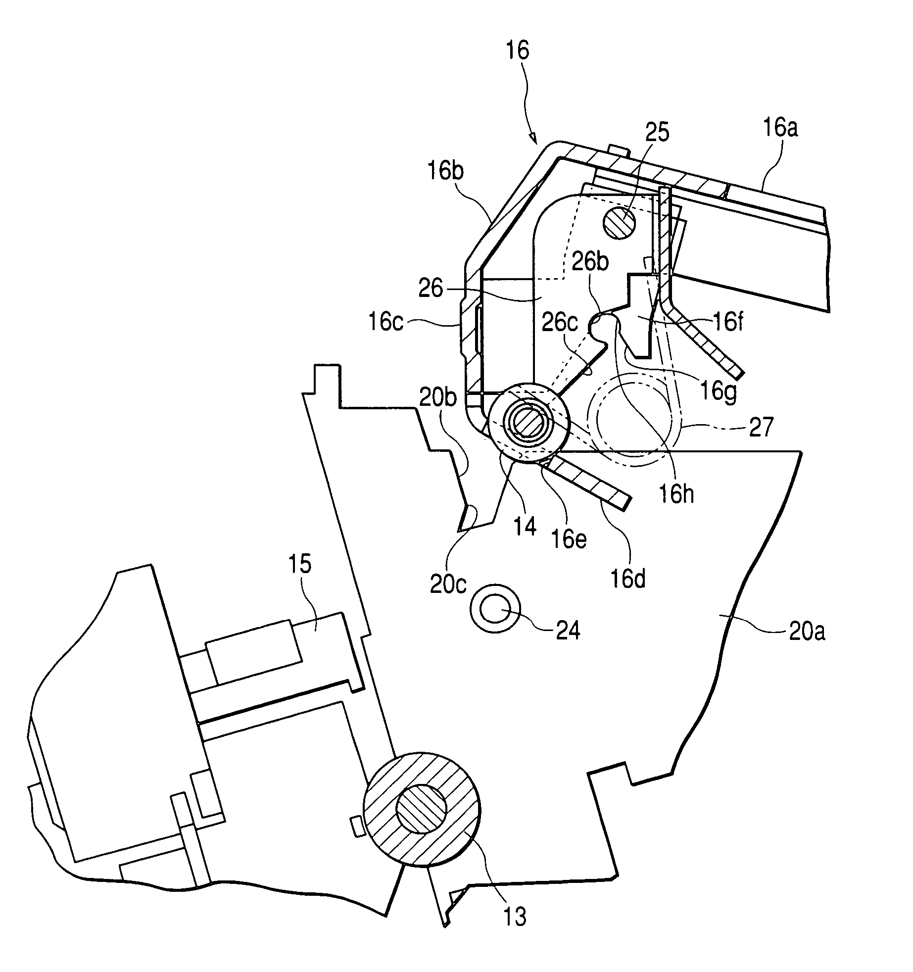
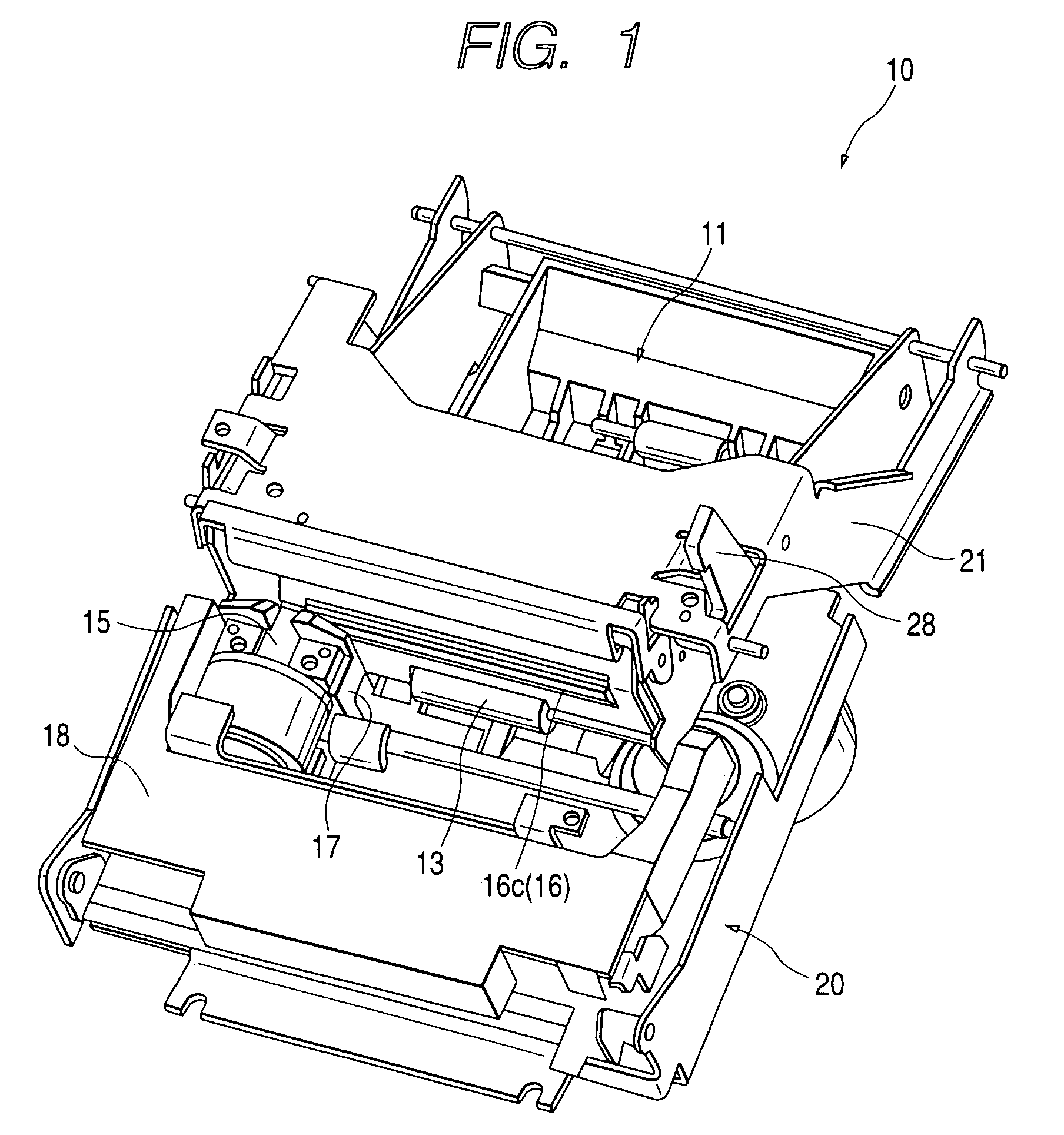
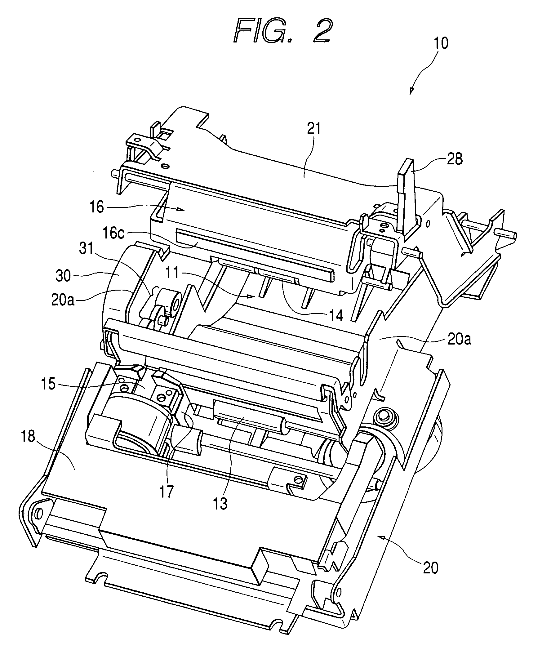
[0029]An embodiment of the invention will be described below with reference to the drawings. FIG. 1 is a perspective view showing a printer unit, illustrating a state in which a cover frame is closed, FIG. 2 is a perspective view showing the printer unit, illustrating a state in which the cover frame is opened (a half-open state), and FIG. 3 is a perspective view showing the printer unit, illustrating a state in which the cover frame is opened (a full-open state). A printer unit 10 shown in these drawings is incorporated in a predetermined housing to constitute a printer. The printer unit 10 comprises a housing 11 for storing a roll-shaped continuous paper P therein, and one end side of the continuous paper P held rotatably in the housing 11 is pulled out of the upper part of the printer unit 10 through a paper path 12. The paper path 12 is provided with a paper feed roller 13 for delivering the continuous paper P, a paper press roller 14 for pushing the continuous paper P against t...


PUM


Abstract

A printer unit comprises a first positioning mechanism and a second positioning mechanism for positioning a platen with respect to a print head when a cover frame is closed. The first positioning mechanism is constituted to restrict a change in the position of the platen to a rotation around a first positioning fulcrum, such as a lock pin. The second positioning mechanism is constituted to restrict the rotation of the platen around a first positioning fulcrum by abutment on a second positioning fulcrum, such as a lock lever spindle.

Description

CROSS-REFERENCES TO RELATED APPLICATIONS[0001]This application is a continuation of U.S. patent application Ser. No. 10 / 347,508, filed Jan. 21, 2003 now U.S. Pat. No. 6,793,419. The entire contents of this application is incorporated herein by reference.BACKGROUND OF THE INVENTION[0002]1. Field of the Invention[0003]The present invention relates to a printer for positioning a platen provided on a cover frame with respect to a print head provided on a body frame when the cover frame is closed.[0004]2. Related Art[0005]In the related art, there is known a printer for storing a continuous paper such as a rolled paper therein and carrying out printing while pulling out the continuous paper. In a printer of this type, to change the continuous paper, it is necessary to manually pull out the continuous paper and take the continuous paper along a predetermined paper path. For this reason, a platen to be disposed in an opposite position to the print head is provided on the cover side of the ...

Claims


Application Information

Patent Timeline
Patent Type & Authority Patents(United States)
IPC IPC(8): B41J11/20B41J11/70B41J15/04
CPCB41J15/042B41J11/20B41J29/42
Inventor NEBASHI, MITSUHIKO
Owner SEIKO EPSON CORP
Why Eureka
Try Eureka