Line generating device

a generation device and line technology, applied in the field of line generation devices, can solve the problems of high cost of laser levels and limited use, and achieve the effect of reducing the cost of laser levels

Active Publication Date: 2006-10-17
BLACK & DECKER INC
View PDF13 Cites 37 Cited by
  • Summary
  • Abstract
  • Description
  • Claims
  • Application Information

AI Technical Summary

Problems solved by technology

Most of these laser levels are expensive due to the optics and electronics involved therein.
However, they typically have limited uses.

Method used


Image

  • Line generating device
  • Line generating device
  • Line generating device

Examples


Embodiment Construction

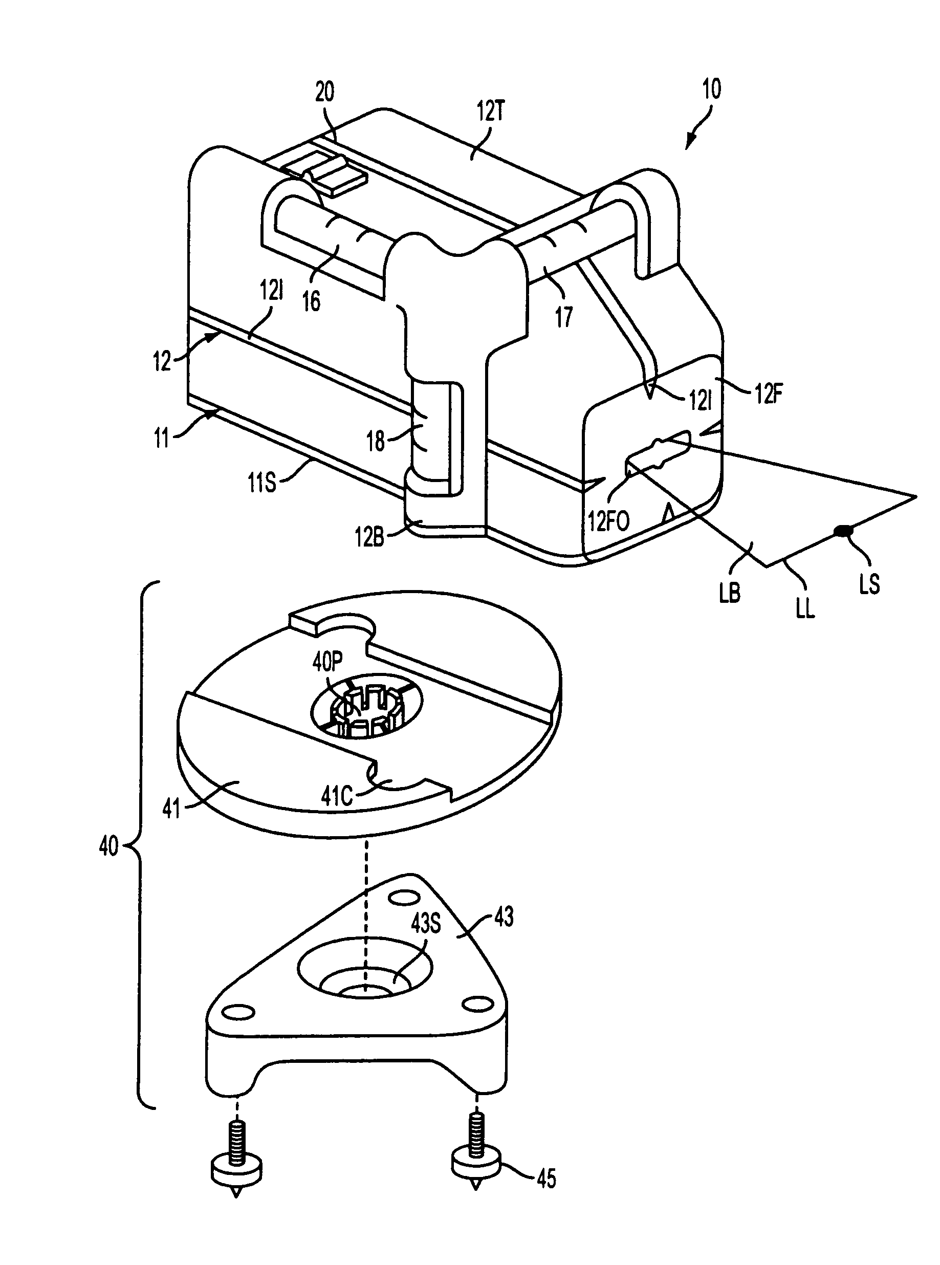
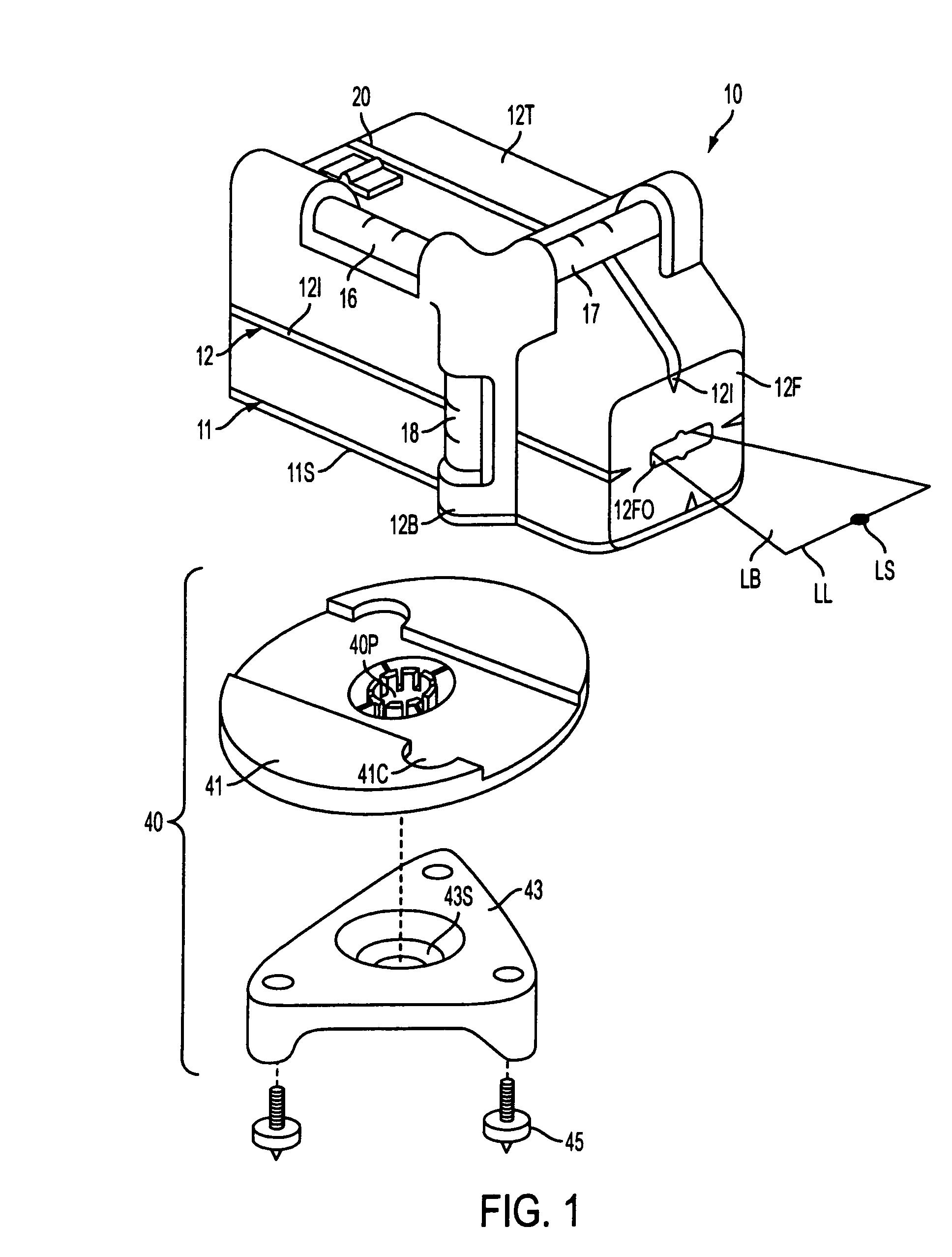
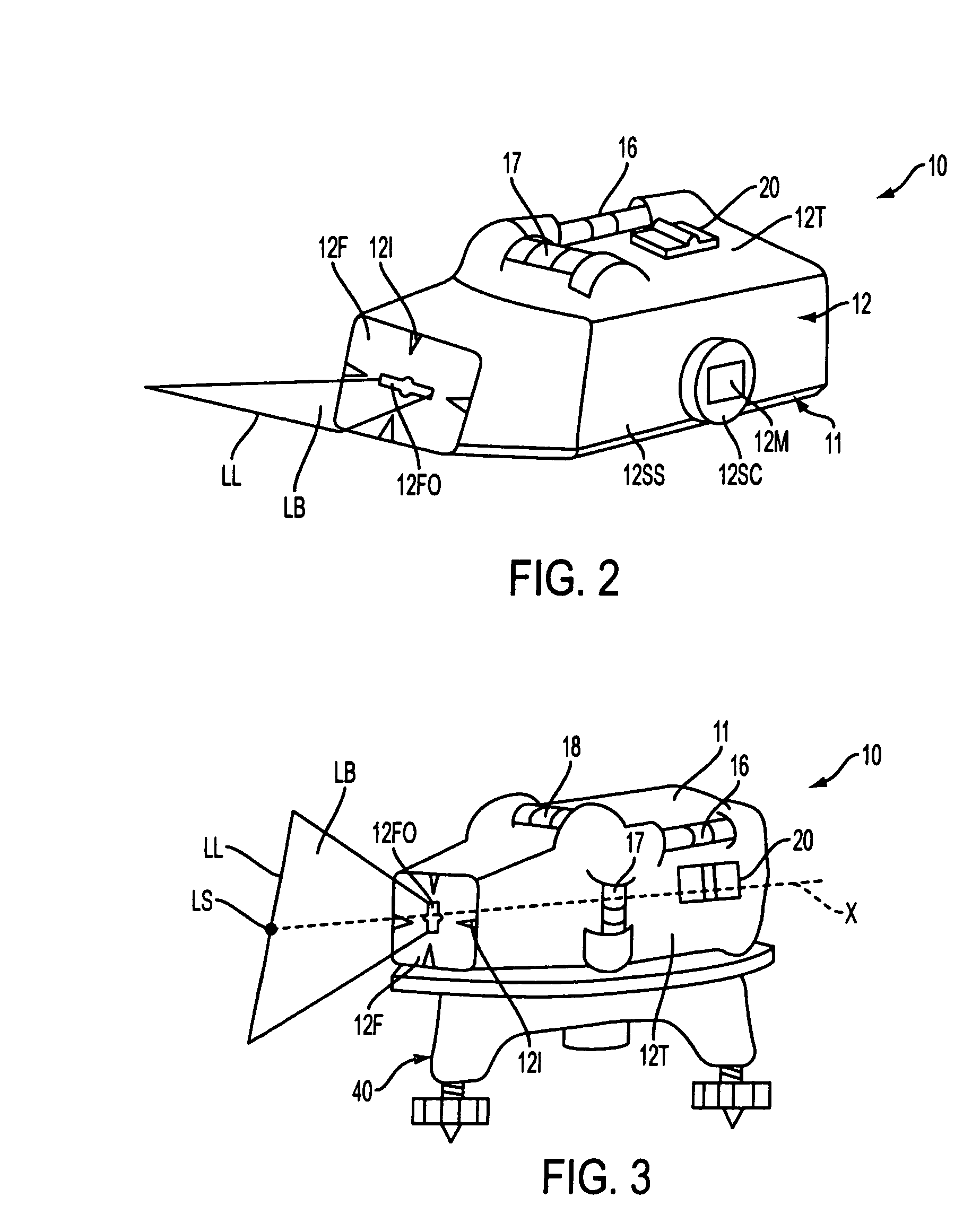
[0025]With reference to FIGS. 1–6, a line-generating device constructed in accordance with the teachings of the present invention is generally indicated by reference numeral 10. Line generating device 10 may comprise a base assembly 11, a housing assembly 12, a support assembly 13 disposed on at least one of the base assembly 11 and housing assembly 12, a laser barrel assembly 14 disposed on the support assembly 13, a lens assembly 15 mounted onto the laser barrel assembly 14, level vials 16, 17, 18 mounted on at least one of the base assembly 11, housing assembly 12 and support assembly 13, a printed circuit board (not shown) with a switch 20 mounted thereon, a battery (not shown) mounted on at least one of the base assembly 11, housing assembly 12 and support assembly 13. Persons skilled in the art are referred to U.S. Application No. 20020178596 and Ser. No. 10 / 822,626 (filed Apr. 12, 2004), both of which are wholly incorporated by reference, for further information on the elemen...


PUM


Abstract

A line generating device may include a housing having a bottom surface, a top surface, a front surface connecting the top and bottom surfaces, a rear surface connecting the top and bottom surfaces, and a side surface connecting the top and bottom surfaces, a support assembly mounted within the housing. In addition, the device may include a light source mounted on the support assembly, and a lens for receiving light and projecting the light in the shape of a fan within a plane. The light plane exits through the front surface. The device is disposable on a reference surface on the bottom, rear and side surfaces.

Description

FIELD OF THE INVENTION[0001]The present invention generally relates to line generating devices and more specifically to laser line generating devices.BACKGROUND OF THE INVENTION[0002]In the construction industry, it is well known to use laser levels for marking reference lines to be used in the layout of different features in a room or structure. Most of these laser levels are expensive due to the optics and electronics involved therein.[0003]Less expensive laser levels that generate a laser line have recently entered the market. However, they typically have limited uses. Accordingly, it is an object of the invention to provide a line generating device that can be used in multiple situations.SUMMARY OF THE INVENTION[0004]In accordance with the present invention, an improved line generating device is employed. The line generating device may include a housing having a bottom surface, a top surface, a front surface connecting the top and bottom surfaces, a rear surface connecting the t...

Claims


Application Information

Patent Timeline
Patent Type & Authority Patents(United States)
IPC IPC(8): G01C15/00
CPCG01C15/004G01C15/008Y10S33/21
Inventor MARSHALL, JAMES D.SERGYEYENKO, OLEKSIY P.DECECCO, STEFANO F.KIMBALL, TED A.MILLIGAN, MICHAEL A.SHAVER, DAVID M.
Owner BLACK & DECKER INC
Why Eureka
Try Eureka