Tray locking mechanism used in an optical disk drive

Inactive Publication Date: 2006-10-24
LITE ON IT
View PDF18 Cites 8 Cited by
  • Summary
  • Abstract
  • Description
  • Claims
  • Application Information

AI Technical Summary

Benefits of technology

[0007]It is therefore a primary objective of the claimed invention to provide a tray locking mechanism for use in a slim optical disk drive for locking and ejecting the tray more smoothly, to solve the above-mentioned problems.

Problems solved by technology

However, sometimes the tray locking mechanism 10 in the prior art lodges so that the tray 2 cannot be ejected smoothly.

Method used


Image

  • Tray locking mechanism used in an optical disk drive
  • Tray locking mechanism used in an optical disk drive
  • Tray locking mechanism used in an optical disk drive

Examples


Embodiment Construction

[0026]The embodiments according to the present invention are related to a slim optical disk drive. Additionally, the present invention can be used in all kinds of optical disk drives including CD-ROM, CD-RW, half-height drives, combo drives, DVD-R / RW, external drives, optical players, and so on. Please note that elements with the same reference numerals are substantially the same through the various embodiments.

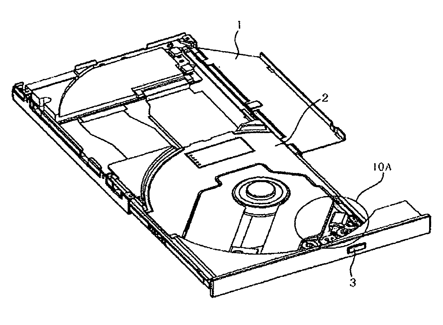
[0027]Please refer to FIG. 7. FIG. 7 is a drawing of a slim optical disk drive in an unlocked situation according to the present invention. The slim optical disk drive includes a main body 1, a tray 2, an ejection button 3, and a tray locking mechanism 10A installed under the tray 2. Please refer to FIG. 8. FIG. 8 is a drawing of the tray locking mechanism 10A of the slim optical disk drive in a locked situation according to the present invention. Please refer to FIG. 9, FIG. 10, FIG. 11, FIG. 12, and FIG. 13. FIG. 9 is an enlargement of the tray locking mechanism 10A. FIG. 1...


PUM


Abstract

An optical disk drive includes a main body and a tray. A tray locking mechanism includes a base fixed to the tray, a locking device installed on the base for combining with or separating from a stop pin of the main body, a transmission device installed on the base for driving the locking device, and a control device installed on the base for stopping the transmission device. When the locking device combines with the stop pin of the main body, the tray can be locked to the main body, and when the transmission device drives the locking device to be separated from the stop pin of the main body, the tray can eject from the main body and the control device can stop the transmission device from rotating.

Description

BACKGROUND OF INVENTION[0001]1. Field of the Invention[0002]The present invention relates to an optical disk drive, and more particularly, to a tray locking mechanism for use in a slim optical disk drive.[0003]2. Description of the Prior Art[0004]Recently, owing to progress of computer technology, prices of optical disk drives are becoming lower. Slim optical disk drives are used for storage devices of notebooks, and because of increasing demand for notebooks on the market the demand for slim optical disk drives is also increasing. In addition, owing to the progress of computer technology, reading speeds of optical disk drives are becoming faster. Please refer to FIG. 1. FIG. 1 is a drawing of a conventional slim optical disk drive in an unlocked situation. The conventional slim optical disk drive includes a main body 1, a tray 2, an ejection button 3, and a tray locking mechanism 10 installed under the tray 2. Please refer to FIG. 2 and FIG. 3. FIG. 2 is a drawing of the convention...

Claims


Application Information

Patent Timeline
IPC IPC(8): G11B33/02G11B33/12
CPCG11B33/121
Inventor HSU, CHENG-CHUNGLEE, IN-SHUENCHUANG, JUI-NAN
Owner LITE ON IT
Why Eureka
Try Eureka