Flow cytometer

a flow cytometer and flow cytometer technology, applied in the field of flow cytometers, can solve the problems of weakening the photoelectrically detected signal, affecting the accuracy of counting and classification, and dispersing goes against the stability of signal detection and high-speed cell-interrogation, so as to enhance the stability of optical signals

Active Publication Date: 2009-07-14
SHENZHEN MINDRAY BIO MEDICAL ELECTRONICS CO LTD
View PDF11 Cites 48 Cited by
  • Summary
  • Abstract
  • Description
  • Claims
  • Application Information

AI Technical Summary

Benefits of technology

[0007]The main object of the present invention is to overcome a prior art problem, that is, the distribution of the optical energy in the cell-interrogation zone of the flow chamber is relatively narrow. Specifically, the present invention aims to provide a flow cytometer, which is capable of distributing the energy of the focused spot substantially uniformly along the direction of the major axis, so as to enhance the stability of optical signals excited by the cells. Another object of the present invention is to provide an optical system for use in the flow cytometer, whereby the accompanying signal of the scattered signals may be eliminated by collimating the light beam.
[0026](1) The present invention employs two sets of cylindrical lens to respectively converge the light beam in two directions, so that the lens parameters in one direction can be flexibly adjusted without affecting the convergence in the other direction, whereby the spot may be flattened in a certain direction.
[0027](2) The present invention takes advantage of two positive cylindrical lenses to converge the collimated light beam. The first cylindrical lens converges the light beam in the flowing direction of the sample flow to an extent of 15 μm-25 μm within the cell-interrogation zone of the flow chamber. The second cylindrical lens converges the light beam in the direction perpendicular to the sample flowing direction. However, the converged focus thereof is not on the sample flow, but deviates therefrom, so as to ensure that the dimension of the converged light beam in the cell-interrogation zone of the flow chamber is within 160 μm-220 μm. Thus the light beam is converged only in these two directions. Further, by adjusting the focal length, the major axis of the spot is much longer than the minor axis, so that the light intensity is uniformly distributed at a segment in the direction of the major axis, whereby flattening of the spot is achieved. Therefore, when the cells are deviated from the sample flow due to some disturbance, the energy of the light beam excited by the cells remains constant. That is, instability of the flow will not lead to instability of the excited optical signal, thus the stability and reliability of the system are improved.
[0028](3) By using an aspheric lens with a large numerical aperture in the present invention, the light beam with a large scattering angle could be collimated successfully. Thereby, the optical system according to the present invention is capable of eliminating the sidelobes of the irradiating spot at the cell-interrogation zone of the flow chamber and avoiding the disturbance of the false pulse of the scattered signal, which renders the result of the detection more accurate. The realization of such accuracy is ensured by the design of the optical system, which is an intrinsic feature, without a need in signal processing for related elimination, so that signal processing becomes simpler and more direct, providing the present invention with improved practicability.

Problems solved by technology

Such an energy distribution goes against the stability of signal detection and high-speed cell-interrogation.
When the routes via which the cell particles flow through the interrogation zone become chaotic due to an increase in detection rate or other causes, the cell flow may deviate from the energy center of the focused spot, leading to a weakening of the photoelectrically detected signal.
As a further result, the scattergram of the detected signals may be subjected to a false appearance, which may affect the accuracy of counting and classification.
Another problem with the prior art cytometer is as follows.
In other words, light with a different height from the optical axis are converged to different locations, so a significant aberration occurs after the light beam passes through the optical system.
However, this approach still has a significant disadvantage in that the main pulse of some smaller cells is usually even smaller than the accompanying pulse of the bigger cells, and consequently the real scattered signal of the small cells would be rejected along with the accompanying pulse of the bigger cells by using the threshold value, which will bring error to the cell analysis.

Method used


Image

  • Flow cytometer
  • Flow cytometer
  • Flow cytometer

Examples


example 1

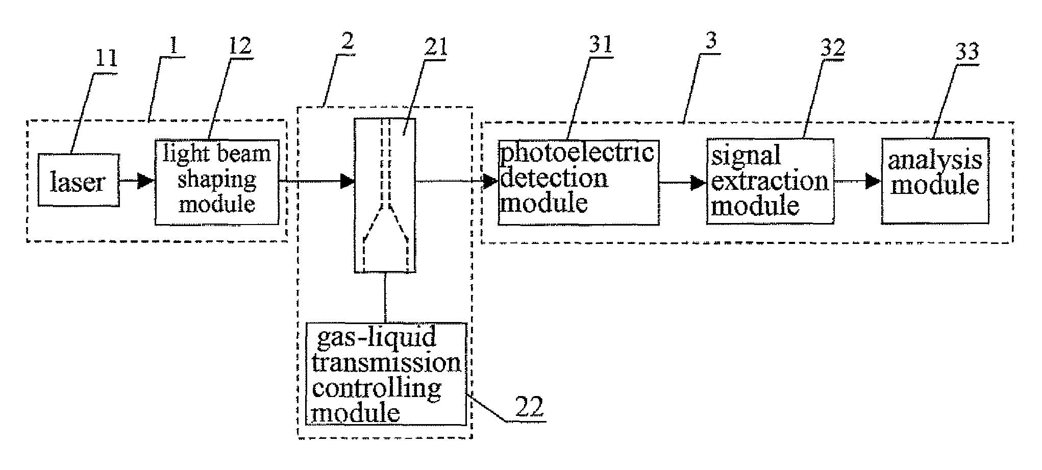
[0046]As shown in FIG. 4, the flow cytometer according to the present embodiment comprises an illuminating unit 1, a sample generation unit 2 and a signal processing unit 3 which are connected in series.

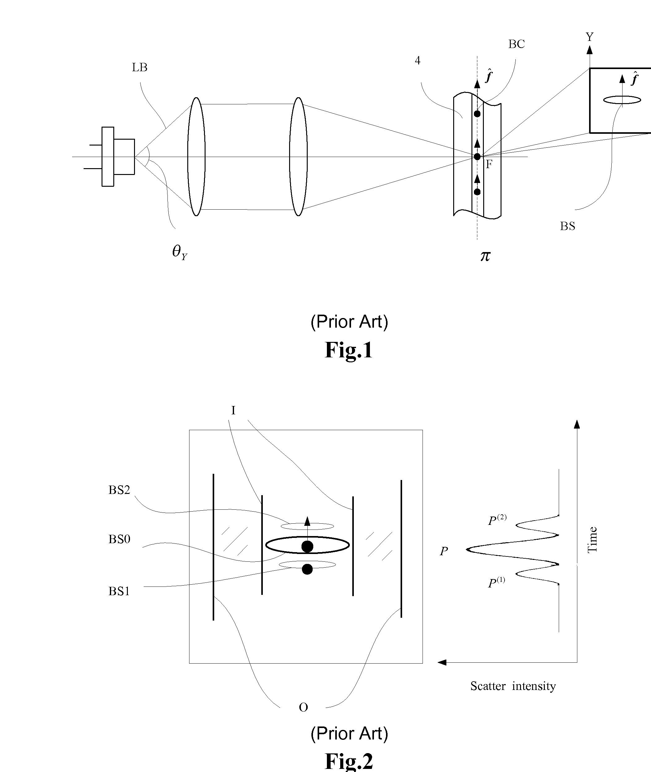
[0047]The illuminating unit 1 comprises a light source and a light beam shaping module 12. The light source is typically a laser 11 such as a gas laser or solid laser, and preferably, a semiconductor laser in the present embodiment, which significantly reduces the structural dimension of the whole system. As shown in FIG. 5, the light beam LB emitted by the semiconductor laser has different divergence angles in two directions. Assuming that the light is transmitted along Z axis, the light beam divergence angle θx in the X direction does not equal to the divergence angle θy in the Y direction. If θx11 in the two directions perpendicular to each other are 30° and 18° respectively, with a maximum output power of 10 mW, operating power of 5 mW and wavelength of 670 nm.

[0048]The light bea...

example 2

[0056]The second embodiment is a further improvement over the first one. To focus the Gauss light beam emitted by the semiconductor laser 11 and having a relatively large angle of divergence onto the interrogation zone of the flow chamber 21, the collimating lens 121 in the light beam shaping module 12 is an aspheric collimating lens with a large numerical aperture, the magnitude of which is at least 0.3. As shown in FIG. 10, the numerical aperture of the single collimating lens 121, which takes the form of an aspheric lens, preferably is about 0.3-0.5, and the shape of its lens surface is defined by the following formula:

[0057]z=cr21+1-(1+k)⁢c2⁢r2+α1⁢r2+α2⁢r4,

wherein, c is the curvature, z is the axial distance of the cross-section from the fixed point, k is a quadratic constant, and r is the radius of the cross-section.

[0058]In addition, the light beam shaping module 12 may comprise more than one aspheric collimating lens 121 with a numerical aperture no less than 0.3.

[0059]As sho...

example 3

[0063]The third embodiment is a further improvement over the first and second embodiments. In the present embodiment, as shown in FIG. 12, the photoelectric detection module 31 comprises two sets of photoelectric signal collecting sub-modules and corresponding photoelectric converters 316A 316B. These two sets of photoelectric signal collecting sub-modules respectively collect optical signals with different scattering angles, and the photoelectric converters perform corresponding photoelectric conversion for the optical signals. In particular, the photoelectric detection module 31 comprises a collimating lens 311, a light-splitting prism 312, annular diaphragms 313A, 313B, condensers 314A, 314B, pinhole diaphragms 315A, 315B and photoelectric converters 316A, 316B.

[0064]The photoelectric signal collecting sub-module is accordingly comprised of the annular diaphragms 313A, 313B and the condensers 314A, 314B, wherein the clear apertures of the annular diaphragms 313A and 313B are uneq...


PUM

PropertyMeasurementUnit
widthaaaaaaaaaa
side lengthaaaaaaaaaa
thickness k0aaaaaaaaaa

Abstract

The present invention relates to a flow cytometer, comprising a light source, a light beam shaping module for collimating and converging a light beam emitted from the light source so that the light beam irradiates samples to be detected, a sample generation unit, which comprises a gas-liquid transmission controlling module and a flow chamber that are interconnected, and a signal processing unit, for collecting, photoelectrically converting and analyzing the scattered beam emitted from the flow chamber. The light beam shaping module comprises a first cylindrical lens and a second cylindrical lens for respectively converging the light beams in two directions. In the present invention, the spot converged at the cell-interrogation zone of the flow chamber is flattened to avoid instability of the fluid which in turn leads to instability of the excited optical signal, and consequently the stability and reliability of the system are improved.

Description

RELATED APPLICATION[0001]The present application claims the priority of the Chinese Patent Application No. 200610062982.2, titled “FLOW CYTOMETER”, which was filed on Sep. 30, 2006, and is incorporated herein by reference in its entirety.FIELD OF THE INVENTION[0002]The present invention relates to a cytometer, in particular, to a flow cytometer.BACKGROUND OF THE INVENTION[0003]Cytometers, as an instrument for counting and classifying various cells, have been widely used in the medical and biological fields. Conventional cytometers typically employ a flow cytometry. Such a cytometer is comprised of a light source, a flow chamber and a photoelectric detection unit. The flow chamber provides an optical cell-interrogation zone, in which a sample flow of cells is encircled in a sheath flow according to the sheath flow principle (i.e., fluid focusing principle), so that the cells pass through the detection passage one by one. The light source, usually a laser, provides an illuminating lig...

Claims


Application Information

Patent Timeline
Patent Type & Authority Patents(United States)
IPC IPC(8): G01N15/02
CPCG01N15/1434
Inventor LUO, CHENGSHAO, HANRONG
Owner SHENZHEN MINDRAY BIO MEDICAL ELECTRONICS CO LTD
Why Eureka
Try Eureka