Tolerance compensation element

a technology of tolerability and compensation element, which is applied in the direction of transportation and packaging, supplementary fittings, building components, etc., can solve the problems of costly installation of known spacing devices and bothersome rejection, and achieve the effect of convenient installation, simple spacing and wide us

Inactive Publication Date: 2009-09-22
SUDDEUTE ALUMINUM MANUFAKTUR
View PDF25 Cites 8 Cited by
  • Summary
  • Abstract
  • Description
  • Claims
  • Application Information

AI Technical Summary

Benefits of technology

[0004]The object of the invention is to provide a simple spacing device that is readily installed and widely usable, the installation preferably being possible without any problems also by untrained personnel.
[0005]To reach this objective, taking into consideration the aforesaid characteristics, the spacing device is provided with a supporting part and a counter-supporting part, said supporting and counter-supporting parts being held together by a screw connection and being displaceable relative to one another for the purpose of adjusting the bridging length, the supporting part and / or the counter-supporting part having an internally disposed gripping seat for the engagement of the adjustment tool. By “internally disposed gripping seat for the adjustment tool” is meant a seat for the adjustment tool that is not located at the periphery of the spacing device or that extends beyond said periphery, but is disposed so that the adjustment tool grips the internal parts of the spacing device without itself extending beyond the said periphery or—in the area of a partial periphery—extends beyond it only insignificantly. In this manner, it is possible to install the spacing device between the carrier part and the roof body from inside the motor vehicle, namely from the passenger compartment. Once this is done, it is possible, also from inside the vehicle, to perform the screw-tightening needed to secure the roof rack or the like. In this case, the spacing device on the one side rests on the carrier part and on the other side is screwed into a thread in the roof rack. The spacing device bridges the gap between the carrier part and the roof body and is capable of transferring to the carrier part the forces generated in the roof rack as a result of installation or use without thereby deforming or unduly stressing the roof body.

Problems solved by technology

During the installation of the roof rack, a solid connection with the carrier part must be ensured, but at the same time no pressure must be exerted on the roof body, pressure that would cause sheet metal deformation and lead to bothersome rejections.
The installation of known spacing devices is costly.

Method used


Image

  • Tolerance compensation element
  • Tolerance compensation element
  • Tolerance compensation element

Examples


Embodiment Construction

[0019]The following description of the preferred embodiments is merely exemplary in nature and is in no way intended to limit the invention, its application, or uses.

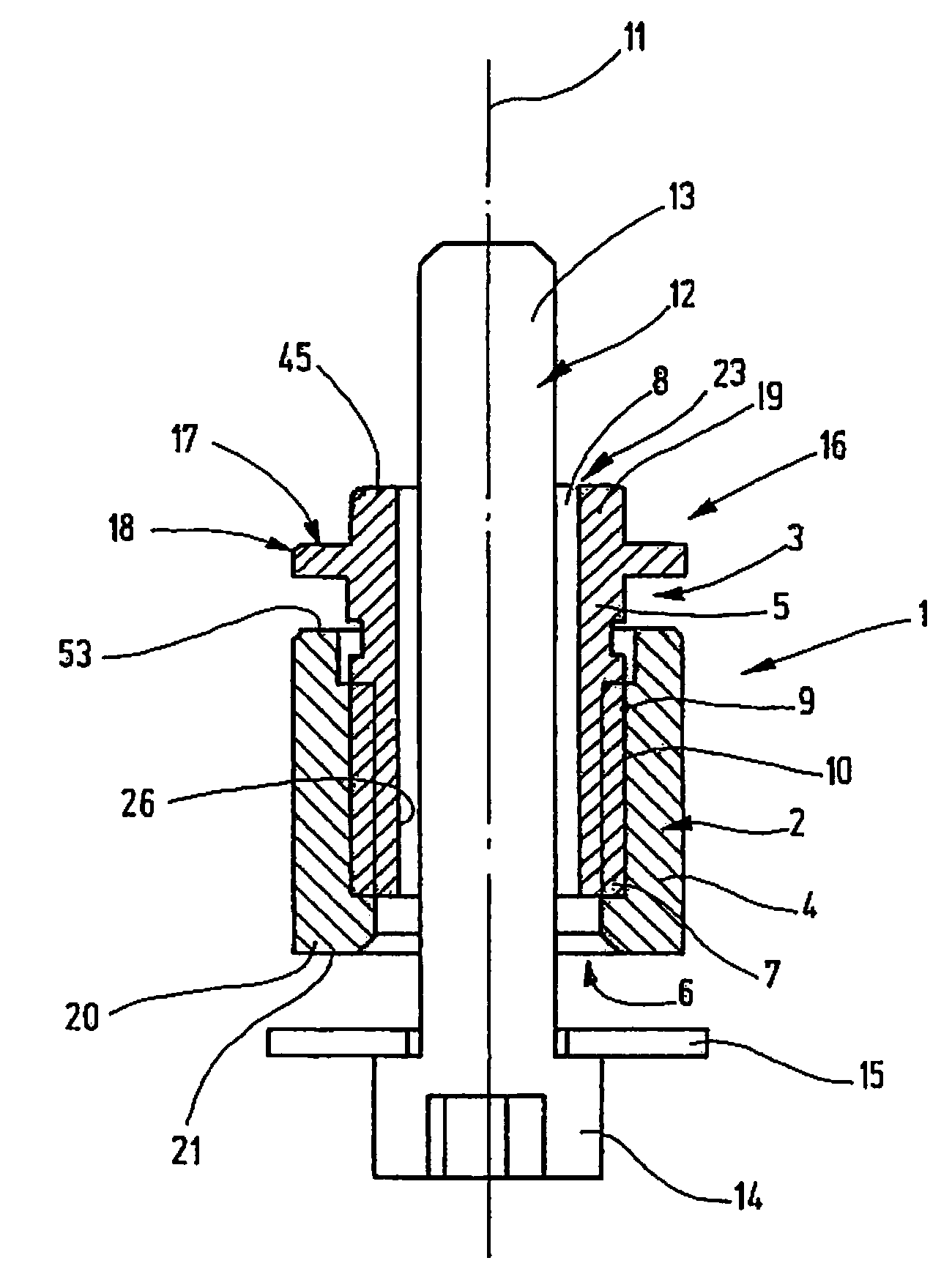
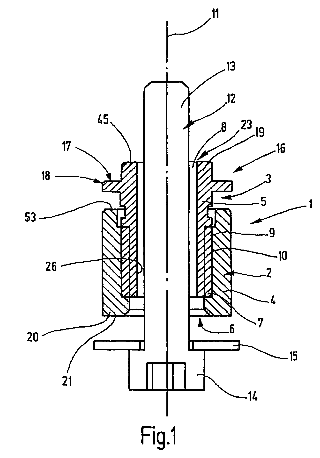
[0020]FIG. 1 shows a spacing device 1 intended for the installation of a roof strip on a vehicle root Spacing device I is provided with a support part 2 and a counter-support part 3. Support part 2 is designed as an outer sleeve 4 and counter-support part 3 as an inner sleeve 5. Outer sleeve 4 has an axial through-bore 6 with inner thread 7. Inner sleeve 5 is provided with an axial through-channel 8. On its outer casing surface 9, inner sleeve 5 is provided with an outer thread 10. Inner thread 7 and outer thread 10 are screwed into each other, meaning that inner thread 7 is axially screwed into outer sleeve 4. In FIG. 1, the axial direction is indicated by midline 11.

[0021]As can be seen from FIG. 1, shaft 13 of screw 12 passes through channel 8 and the corresponding part of through-bore 6. Head 14 of screw 12 is provi...


PUM


Abstract

The invention refers to a spacing device for bridging a gap between a carrier part and a roof body and intended for fastening a roof rack, roof rail, roof strip or the like on a vehicle roof, with a support part and a counter-support part, the support part and the counter-support part being held together by a screw connection and being displaceable relative to one another to allow the adjustment of the bridging length, the support part and / or counter-support part being provided with an internally disposed adjustment tool-gripping seat intended for the manipulation and / or adjustment of the bridging length.

Description

FIELD OF THE INVENTION[0001]The invention refers to a spacing device for bridging a gap between a carrier part and a roof body for the purpose of fastening a roof rack, roof rail, roof strip or the like to a vehicle roof.BACKGROUND OF THE INVENTION[0002]Roof racks, roof rails, roof strips or the like when installed on the vehicle roof of a vehicle do not rest on a roof body consisting of thin sheet metal, but by means of a spacing device are connected to a carrier part. The carrier part can absorb the forces generated by heavy roof loads and, in particular, forces that are to be expected in accident situations (major deceleration). The carrier part cannot be seen from the outside, because it is disposed below the sheet metal of the roof body. The carrier part cannot be seen from the interior space of the vehicle, either, because it is covered by the interior trim (headliner). Between the underside of the roof body and the top side of the carrier part there is present a gap which bec...

Claims


Application Information

Patent Timeline
Patent Type & Authority Patents(United States)
IPC IPC(8): B60R9/04
CPCB60R9/04
Inventor BINDER, HANSBINDER, OTTMARSCHABEL, WOLFGANG
Owner SUDDEUTE ALUMINUM MANUFAKTUR
Why Eureka
Try Eureka